Speed Displaying Device and Speed Displaying Method

a technology of speed display device and speed display method, which is applied in the direction of simultaneous indication of multiple variables, instruments, transportation and packaging, etc., can solve the problems of hard to visually recognize whether the vehicle is accelerating or decelerating, and the target speed of the vehicl

Inactive Publication Date: 2014-07-03
YAZAKI CORP
View PDF8 Cites 14 Cited by
  • Summary
  • Abstract
  • Description
  • Claims
  • Application Information

AI Technical Summary

Benefits of technology

[0032]According to the speed displaying device of the compositions of the above (1) to (5) and the speed displaying method of the steps of the above (6) to (10), because the speed difference region which indicates the size of the difference between the current speed and the target speed with an area is displayed at a position near the scale of the speedometer, it is easy to visually recognize the region that is the difference between the set speed and the vehicle speed at the time of automatic cruise traveling. Besides, it becomes easy to visually recognize whether the vehicle is accelerated or decelerated, and the

Problems solved by technology

However, in the above conventional speed displaying device, there are the following problems.
Further, because only the difference between the position of the pointer which indicates the vehicle speed and the

Method used


Image

  • Speed Displaying Device and Speed Displaying Method
  • Speed Displaying Device and Speed Displaying Method
  • Speed Displaying Device and Speed Displaying Method

Examples


Embodiment Construction

[0040]A speed displaying device and a speed displaying method in the embodiment of the present disclosure are described using the figures. The speed displaying device of the embodiment is carried in a vehicle, and is applied to a digital speedometer that performs a graphic display.

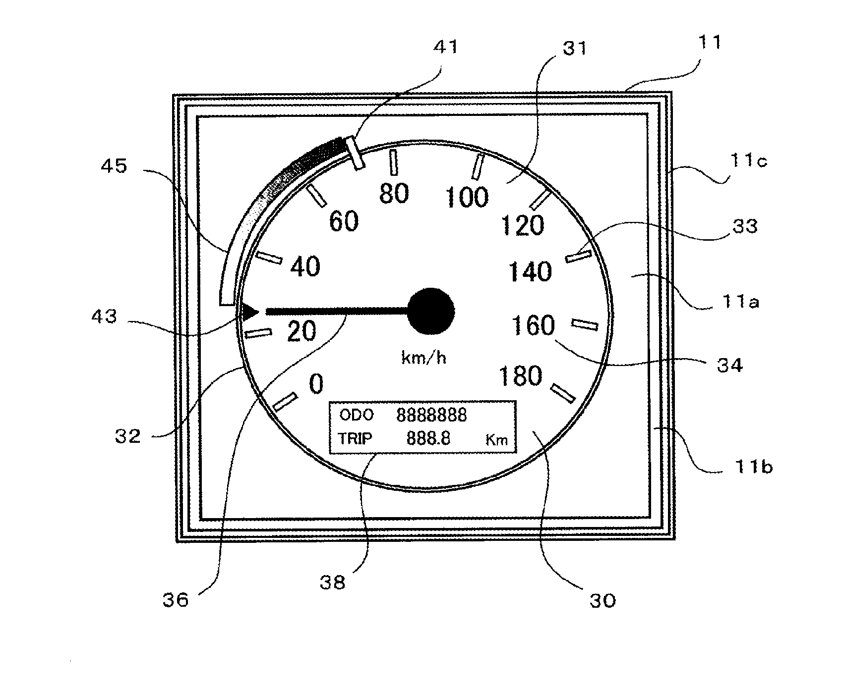
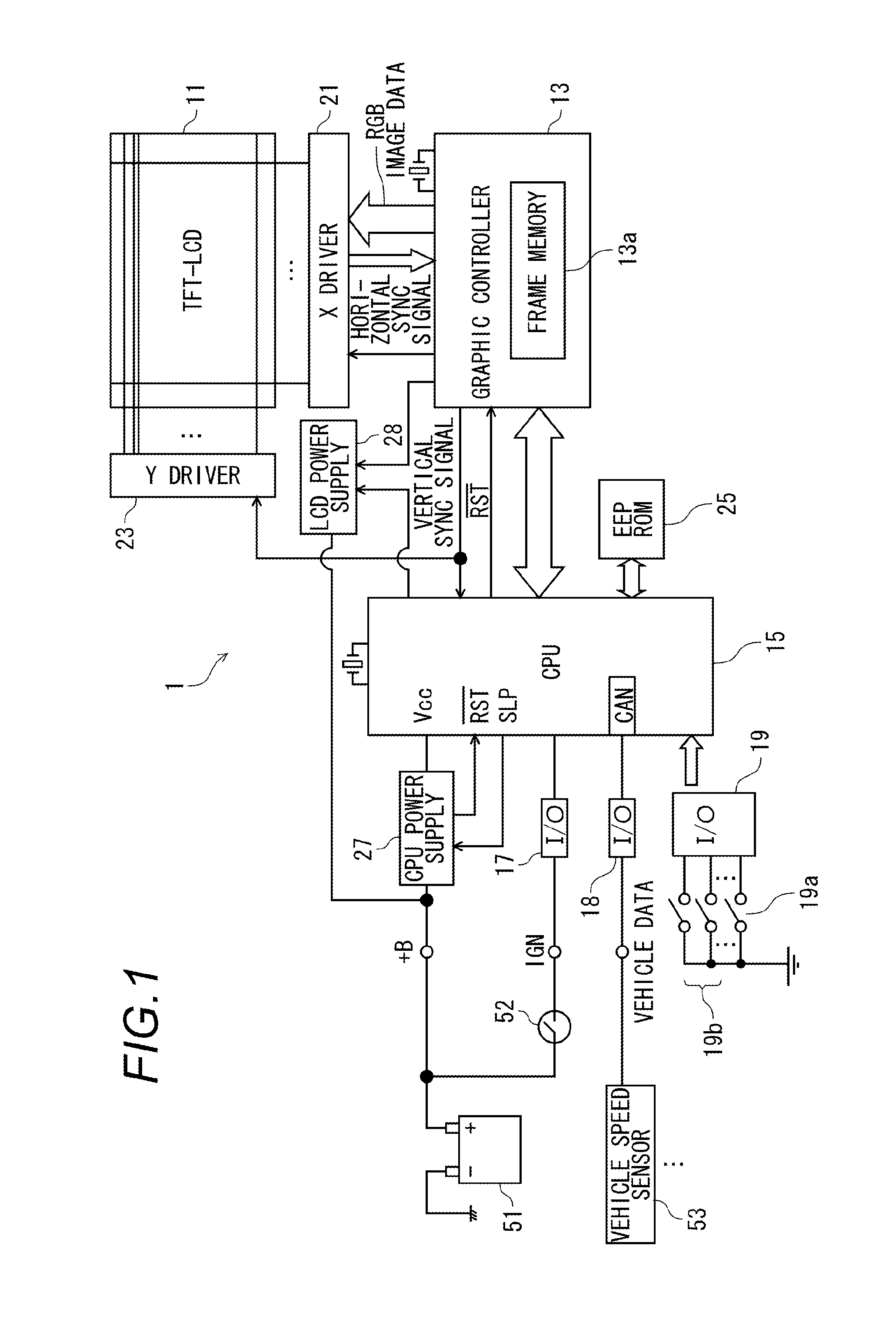
[0041]FIG. 1 is a view which illustrates the composition of a digital speedometer 1 that is the speed displaying device in the embodiment. The digital speedometer 1 has a display panel 11 which is a part of a meter panel of the vehicle, a graphic controller 13, a CPU (controller) 15, and various I / O interfaces 17, 18 and 19 which are connected to the CPU 15.

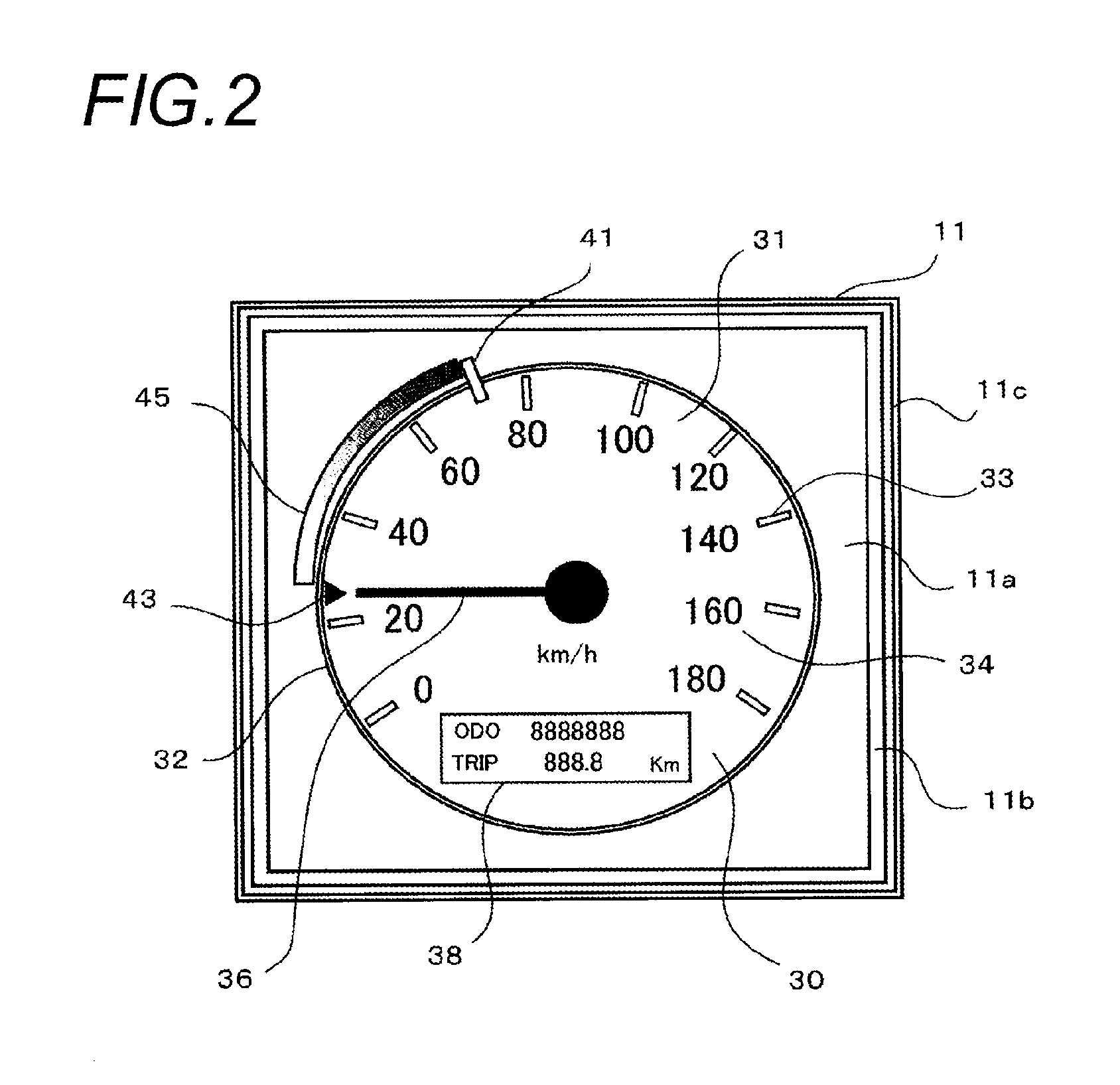
[0042]The display panel 11 has a TFT liquid crystal display (TFT-LCD) 11 a which performs the graphic display, and a front glass 11c which is provided in front of the TFT-LCD 11a by sandwiching an inside part 11b (refer to FIG. 2). The display panel 11 is driven by an X driver 21 which applies a voltage in response to a horizontal sync signal and a Y dr...


PUM


Abstract

A speed displaying device is provided in a vehicle that travels to reach a set target speed, and displays a speedometer which indicates a speed of the vehicle. The speed displaying device includes a speedmeter having a scale and a controller that controls to display a pointer pointed position which indicates a position of current speed of the vehicle in the scale of the speedometer, a speed setting position which indicates a position of the target speed in the scale of the speedometer, and a speed difference region which indicates the size of the difference between the current speed and the target speed with an area on the speed meter. The speed difference region is displayed at a position near the scale of the speedometer.

Description

CROSS REFERENCE TO RELATED APPLICATIONS[0001]This application is a continuation of PCT application No. PCT / JP2012 / 073551, which was filed on Sep. 7, 2012 based on Japanese Patent Application (No. 2011-195374) filed on Sep. 7, 2011, the contents of which are incorporated herein by reference.BACKGROUND OF THE INVENTION[0002]1. Field of the Invention[0003]The invention relates to a speed displaying device and a speed displaying method which display a speedometer that indicates the speed of a vehicle.[0004]2. Description of the Related Art[0005]Conventionally, there is such kind of speed displaying device which displays a vehicle speed and a set speed on a meter which performs a graphic display at the time of automatic cruise traveling which makes an automobile to automatically run at the set speed. FIG. 6 is a view illustrating a display panel of the conventional speed displaying device. This display panel 111 has a TFT liquid crystal display (TFT-LCD) 111a in front of which a piece of...

Claims


Application Information

Patent Timeline
IPC IPC(8): G01P1/11
CPCG01P1/11B60K37/02B60K31/0008B60K31/185B60K35/00G01P1/08G01D7/04G01D13/24B60W2540/12B60K2310/242B60K2310/20B60K2310/22B60K2370/11B60K2370/152B60K2370/154B60K2370/155B60K2370/188B60K2370/698B60W2520/10G01D2207/30
Inventor OISHI, YUKIO
Owner YAZAKI CORP
Why Eureka
Try Eureka