Method and System for Wireless Power Transfer Calibration

Active Publication Date: 2014-07-03
AVAGO TECH INT SALES PTE LTD
View PDF4 Cites 70 Cited by
  • Summary
  • Abstract
  • Description
  • Claims
  • Application Information

AI Technical Summary

Problems solved by technology

However, the conventional systems are particularly susceptible to power transfer efficiency changes during field operation.
When one or more of these factors stra

Method used


Image

  • Method and System for Wireless Power Transfer Calibration
  • Method and System for Wireless Power Transfer Calibration
  • Method and System for Wireless Power Transfer Calibration

Examples


Embodiment Construction

[0014]The following Detailed Description refers to accompanying drawings to illustrate exemplary embodiments consistent with the disclosure. References in the Detailed Description to “one exemplary embodiment,”“an exemplary embodiment,”“an example exemplary embodiment,” etc., indicate that the exemplary embodiment described may include a particular feature, structure, or characteristic, but every exemplary embodiment may not necessarily include the particular feature, structure, or characteristic. Moreover, such phrases are not necessarily referring to the same exemplary embodiment. Further, when a particular feature, structure, or characteristic is described in connection with an exemplary embodiment, it is within the knowledge of those skilled in the relevant art(s) to affect such feature, structure, or characteristic in connection with other exemplary embodiments whether or not explicitly described.

[0015]The exemplary embodiments described herein are provided for illustrative pur...


PUM


Abstract

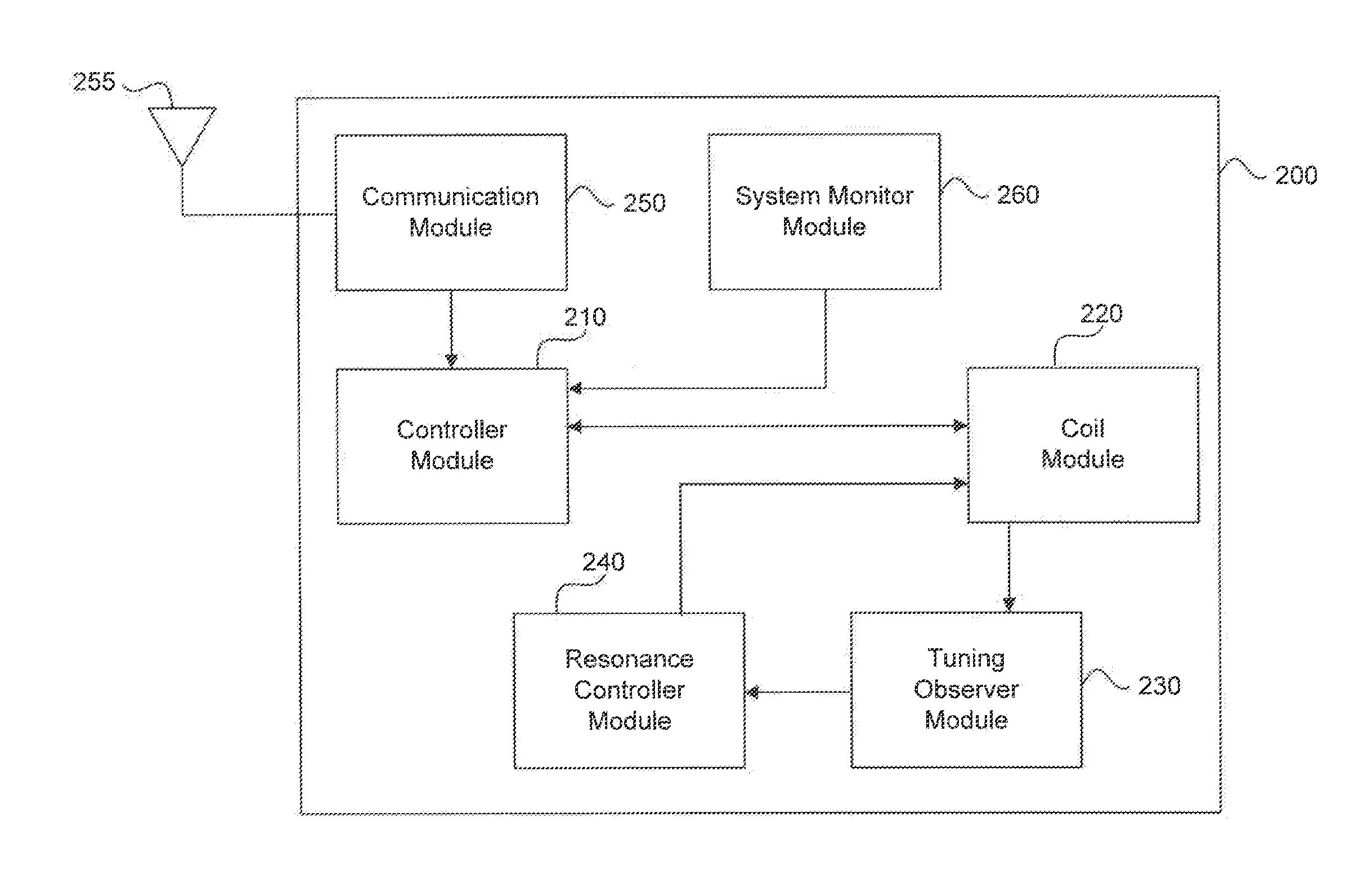
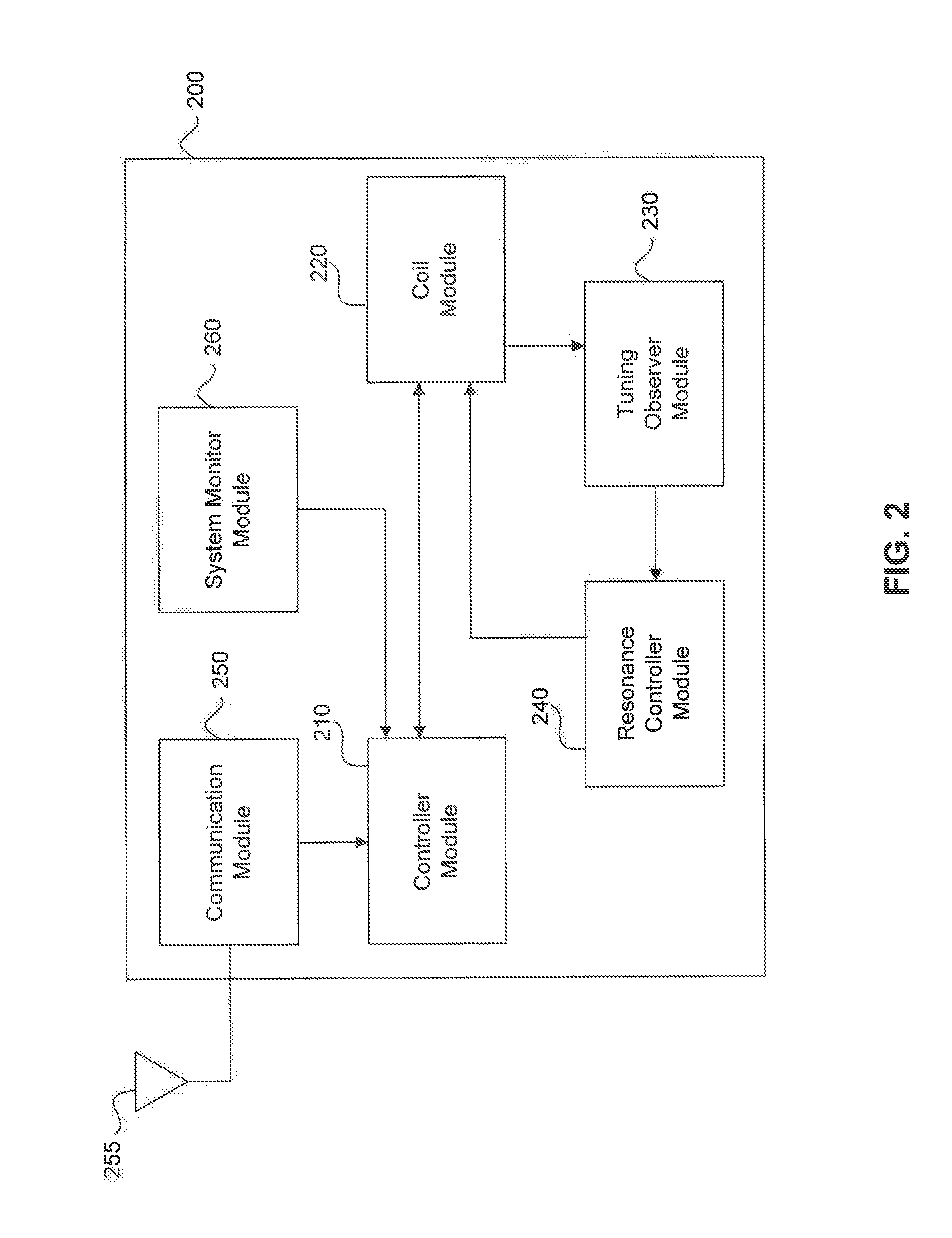
In a WPT system, varying parameters, such as coupling coefficient, may cause the system to fall out of resonance and/or tuning. By monitoring one or more signals within a coil module of the WPT device, this detuning can be detected. Moreover, the WPT system can retune itself by modifying one or more parameters in a transmitting WPT device and/or a receiving WPT device. For example, coil circuits in the transmitting and/or receiving WPT devices can be configured to allow for adjusting of effective capacitance, effective inductance, load resistance, and/or load inductance. In addition, frequency can be modified to permit adjusting power transfer efficiency.

Description

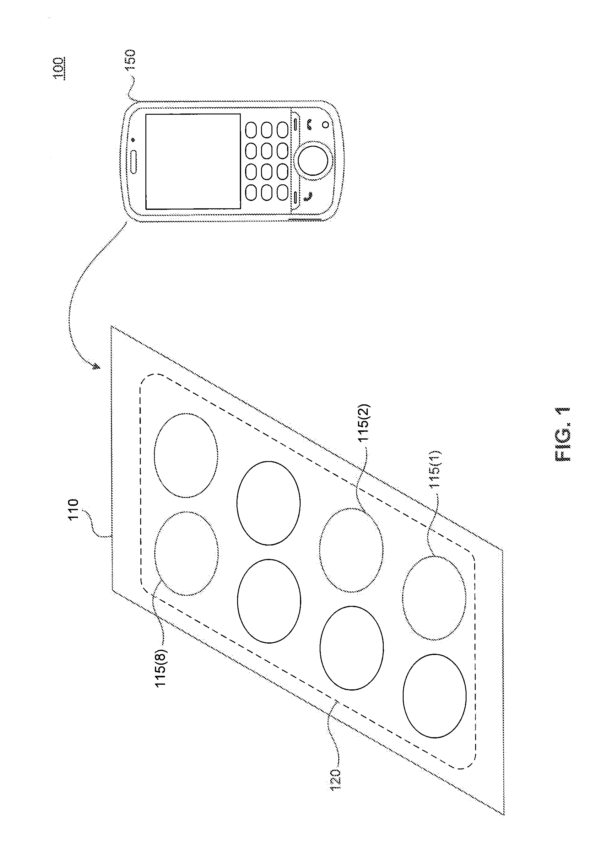
CROSS-REFERENCE TO RELATED APPLICATIONS[0001]This application claims the benefit of U.S. provisional application 61 / 747,057, filed Dec. 28, 2012, which is incorporated herein by reference in its entirety.FIELD[0002]The disclosure relates to wireless power transfer, and more specifically performing calibration within a wireless power transfer system.BACKGROUNDRelated Art[0003]Wireless power transfer stations, such as power pads, have recently become known. Conventional wireless power transfer systems are calibrated during manufacturing to account for component tolerances, manufacturing tolerances, etc. However, the conventional systems are particularly susceptible to power transfer efficiency changes during field operation.[0004]For example, the efficiency of power transfer in conventional wireless power transfer systems is dependent on several factors, including the alignment of the transmitting coil and the receiving coil, the resonance of the system, the tuning of the system, and ...

Claims


Application Information

Patent Timeline
IPC IPC(8): H02J7/00H04B5/00
CPCH04B5/0037H02J7/0052H04B5/0031H04B5/0081H02J50/90H02J50/12H02J7/00034H02J50/70H02J50/60
Inventor WALLEY, JOHN
Owner AVAGO TECH INT SALES PTE LTD
Why Eureka
Try Eureka