Information processing apparatus and method of controlling the same

Active Publication Date: 2014-07-03
CANON KK
View PDF3 Cites 10 Cited by
  • Summary
  • Abstract
  • Description
  • Claims
  • Application Information

AI Technical Summary

Benefits of technology

[0009]In the present specification, an apparatus and method are disclosed according to which, when a PC is to newly join a pre-existing i

Problems solved by technology

However, with analog connections, there are problems in that it is time-consuming to connect devices, it is difficult to connect from a remote location, and it is not possible to connect multiple PC

Method used


Image

  • Information processing apparatus and method of controlling the same
  • Information processing apparatus and method of controlling the same
  • Information processing apparatus and method of controlling the same

Examples


first embodiment

[0022]Examples of preferred embodiments of the present invention will be described in detail below with reference to the accompanying drawings.

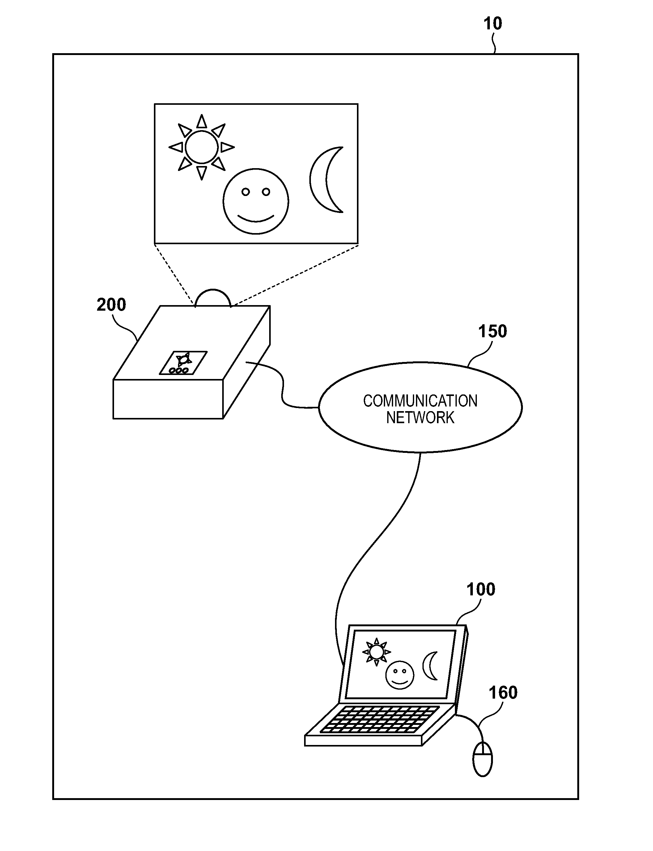
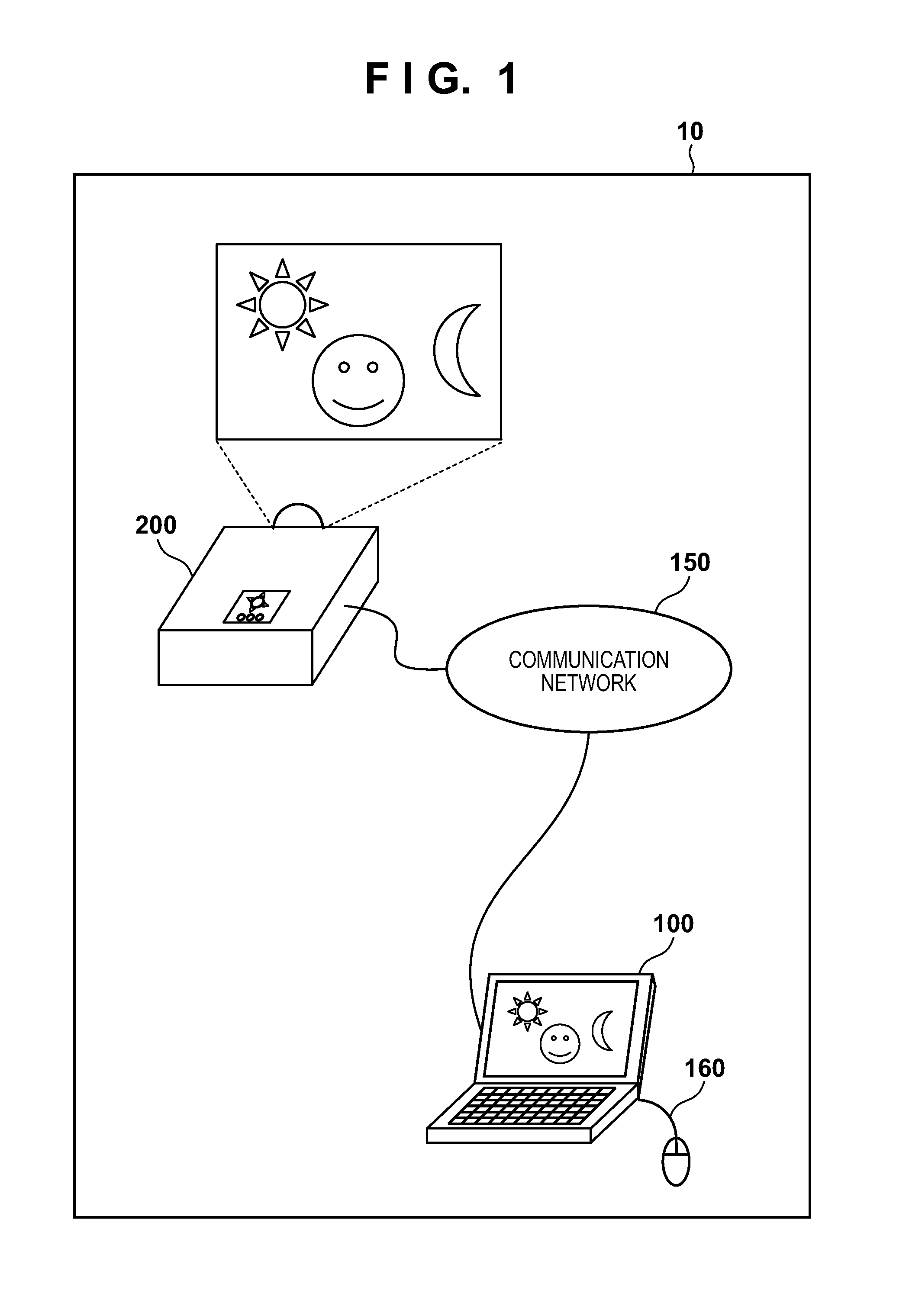
[0023]FIG. 1 is a diagram showing an example of an image transfer system in which an information processing apparatus and an image displaying apparatus of the first embodiment are communicably connected. An image transfer system 10 of the present embodiment includes a PC 100 that is an example of an information processing apparatus that functions as an image transfer apparatus, and a projector 200 that is an example of an image displaying apparatus. The PC 100 and the projector 200 can each be connected to an external device via a LAN or the like, and in the present embodiment, the PC 100 and the projector 200 are communicably connected to each other via a communication network 150. Note that the communication network 150 may be wired or wireless.

[0024]To give a simple description of the roles of each device, the PC 100 can transmit image sig...

second embodiment

[0078]In the above-described first embodiment, the PC 100 generated a group information image and caused the projector 200 to display it, but the present invention is not limited to this. In a second embodiment, a configuration will be described in which the projector 200 creates and projects the group information image. An image transfer system configured by the PC 100 and the projector 200 of the second embodiment will be described below with reference to FIG. 10. Note that since the configurations of the PC 100 and the projector 200 of the second embodiment are similar to those in the first embodiment (FIG. 1 to FIGS. 3A to 3D), the description thereof will not be repeated.

[0079]It is assumed that a user A of the PC-A presses the start information display button 405 of the GUI 400 (step S801). The CPU 101 of the PC-A that detected that the start information display button 405 was pressed performs control of the communication unit 106 in order to transmit an instruction to start t...


PUM


Abstract

Upon detecting an instruction for starting the display of information relating to a network group that is formed via a network and includes an image displaying apparatus, an information processing apparatus that is connected to the image displaying apparatus via the network transmits an instruction for causing a group information image including information relating to the network group to be displayed to the image displaying apparatus via the network.

Description

BACKGROUND OF THE INVENTION[0001]1. Field of the Invention[0002]The present invention relates to an image transfer system that performs display by transmitting an image generated by an information processing apparatus such as a personal computer to an image displaying apparatus such as a projector.[0003]2. Description of the Related Art[0004]In recent years, projectors that cause image signals received from an information processing apparatus such as a personal computer (hereinafter referred to as a “PC”) to be projected onto a screen have often been used when giving presentations during meetings, workshops, and the like. Normally, PCs and projectors perform reception and transmission of image signals via an analog connection using an analog RGB cable. However, with analog connections, there are problems in that it is time-consuming to connect devices, it is difficult to connect from a remote location, and it is not possible to connect multiple PCs at the same time. For these reason...

Claims


Application Information

Patent Timeline
IPC IPC(8): G06F3/14
CPCG06F3/1454G06F3/0482G09G3/002G09G5/14G09G2354/00G09G2370/02G09G2370/20H04W4/08
Inventor OKA, NOBUHIRO
Owner CANON KK
Why Eureka
Try Eureka