Roll medium supporting device and recording apparatus

Inactive Publication Date: 2014-07-03
SEIKO EPSON CORP
View PDF2 Cites 8 Cited by
  • Summary
  • Abstract
  • Description
  • Claims
  • Application Information

AI Technical Summary

Benefits of technology

[0010]With this configuration, the first positioning section and the second positioning section on the shaft member are disposed at different positions both in the axis direction and in the circumferential direction of the shaft member. Accordingly, in spite of the positions being close in the axis direction, the first positioning section and the second positioning section do not overlap with each other. As a result, positioning of the supporting member at the first positioning section and the second positioning section can be selectively performed by selectively engaging the engagement section of the supporting member with the first positioning section and the second positioning section. Therefore, it is possible to position and support a plurality of roll media having widths close to each other without replacing the shaft member.
[0011]In the above roll medium supporting device, it is preferable that the insertion hole includes a first hole engagement section and a second hole engagement section, and the shaft member includes a shaft engagement section such that, when the shaft member is inserted into the insertion hole at a first angle in a rotation direction about an axis of the shaft member, the shaft member engages the first hole engagement section in the rotation direction, and, when the shaft member is inserted into the insertion hole at a second angle in a rotation direction about the axis of the shaft member, the shaft member engages the second hole engagement section in the rotation direction.
[0012]With this configuration, it is possible to position the shaft member in the rotation direction by inserting the shaft member into the insertion hole at different positional aspects in the rotation direc

Problems solved by technology

As a consequence, there is a risk that the grooves used for positioning of the regulation members which correspond to the paper rolls to be replaced having sizes (widths) significantly close to each other overlap with each other.
Ac

Method used


Image

  • Roll medium supporting device and recording apparatus
  • Roll medium supporting device and recording apparatus
  • Roll medium supporting device and recording apparatus

Examples


Example

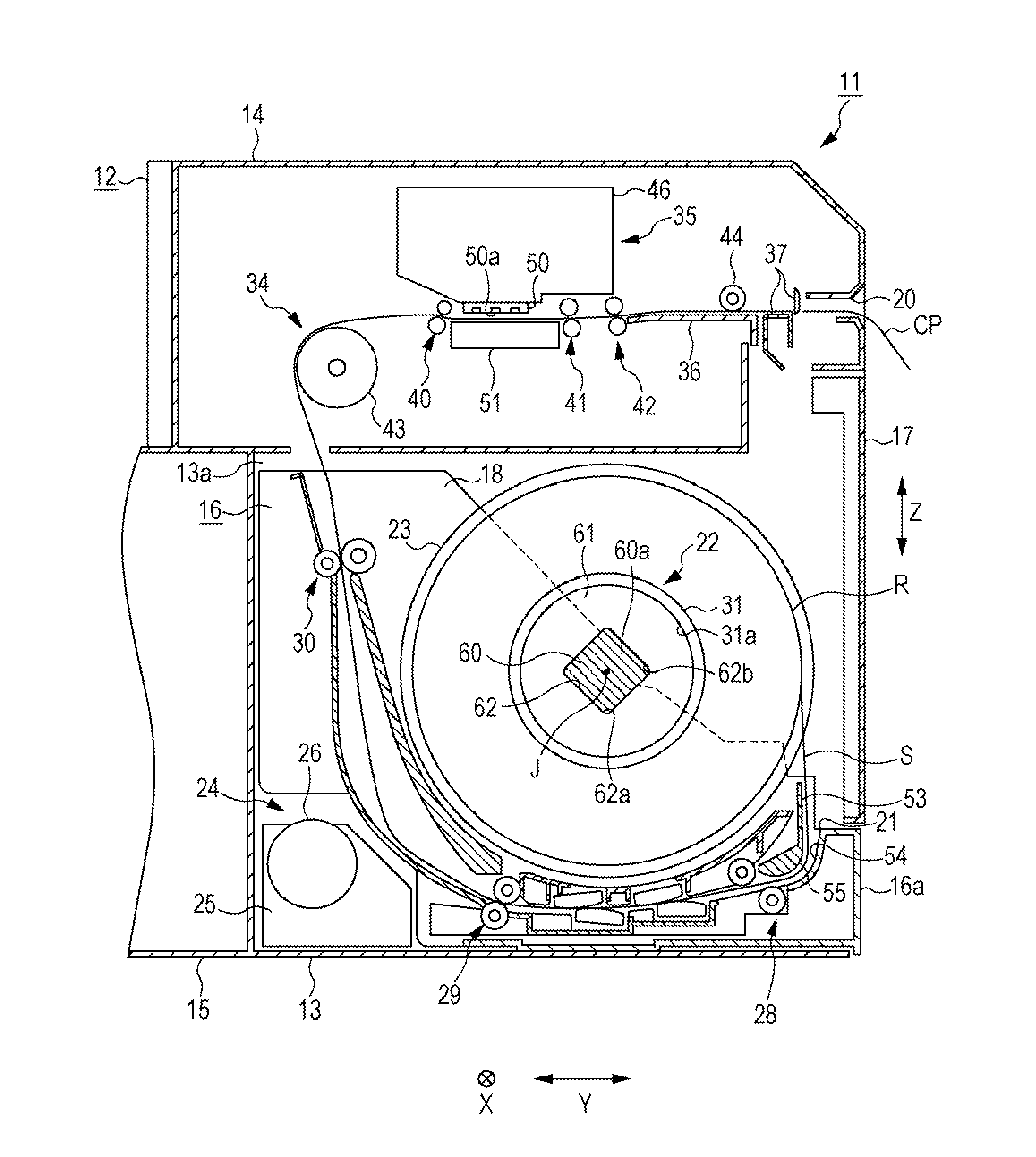
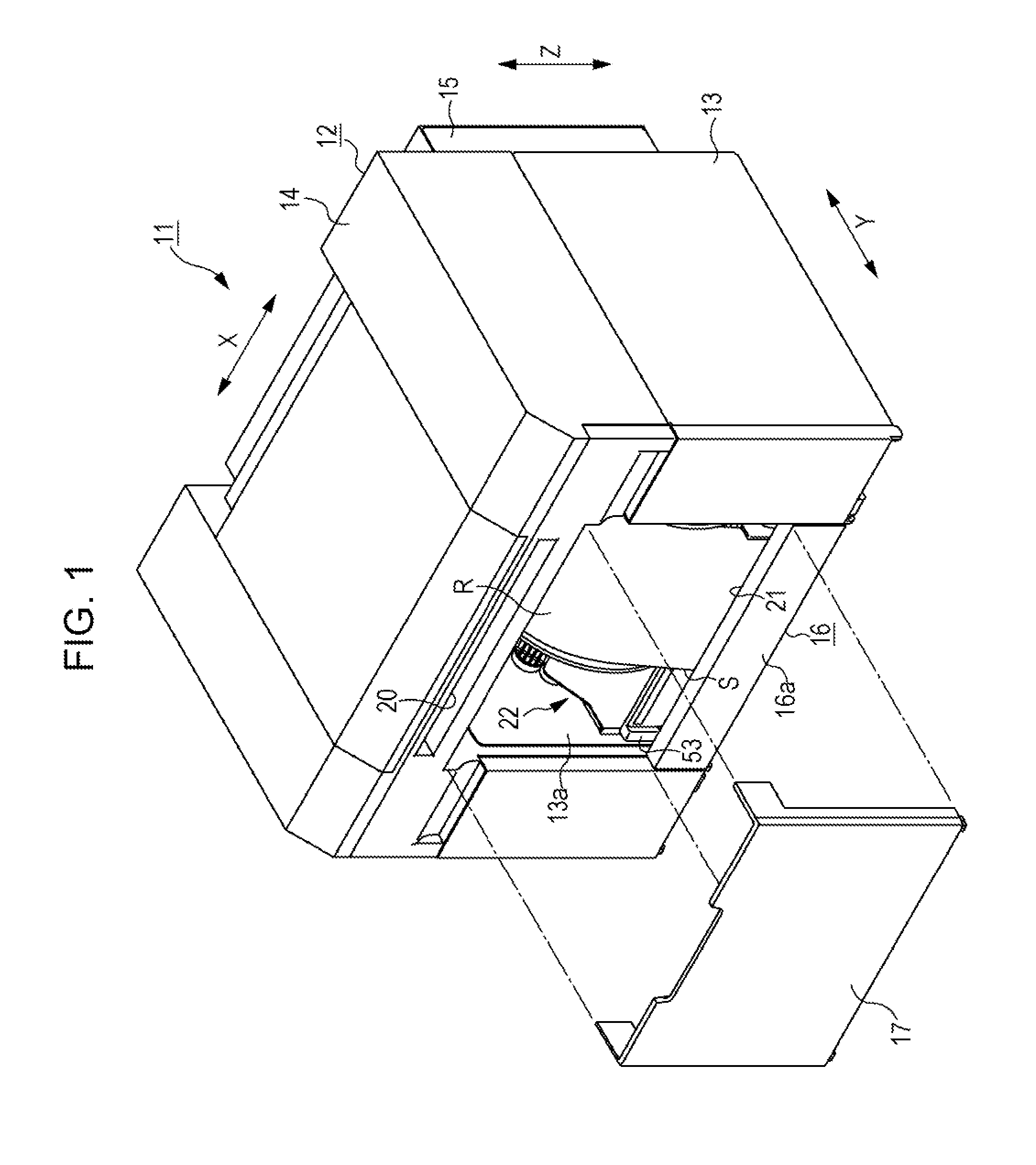
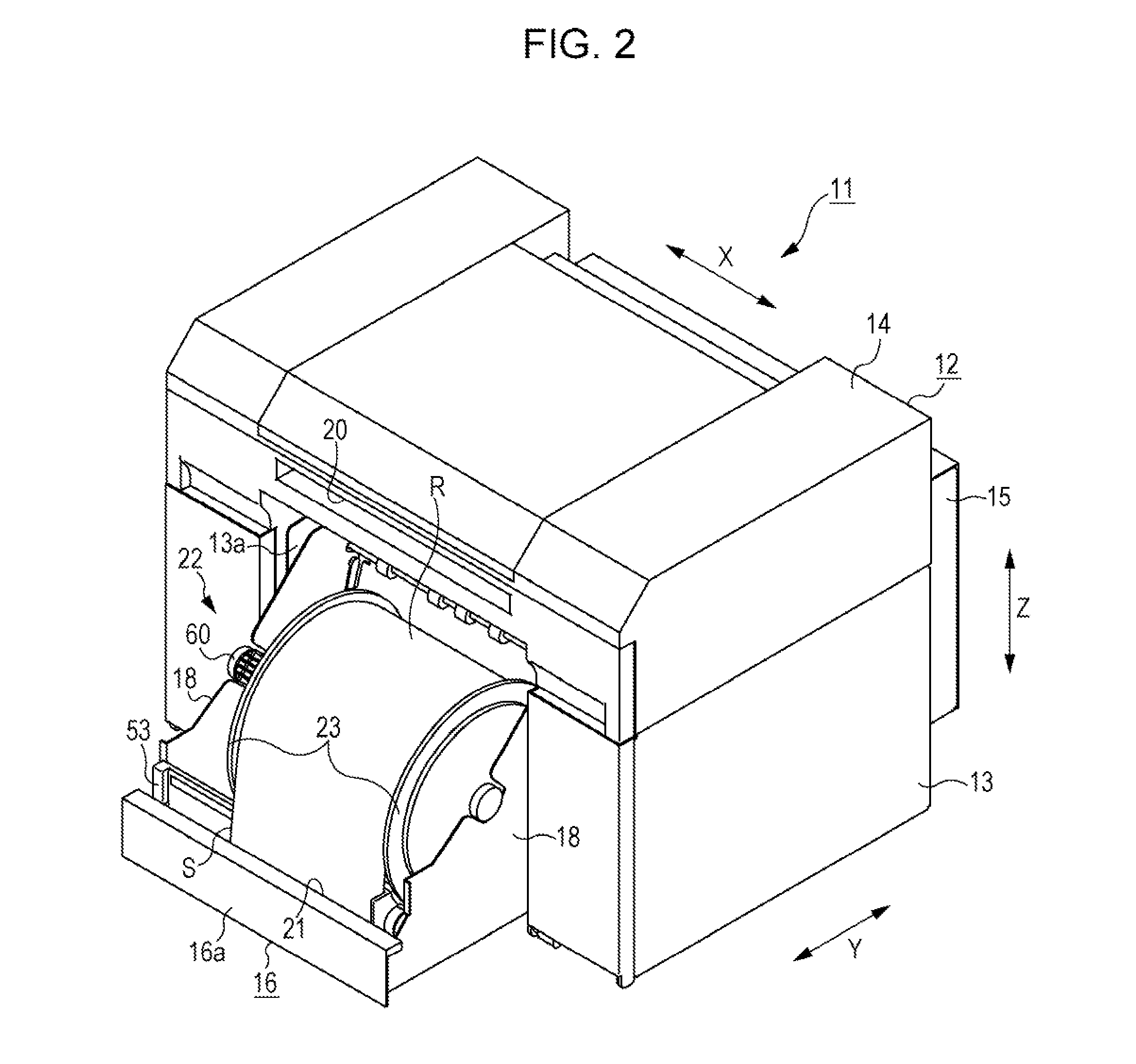
[0027]An embodiment in which a recording apparatus is implemented as an ink jet printer will be described below with reference to the drawings. As shown in FIG. 1, an ink jet printer 11 which is an example of recording apparatus includes an apparatus body 12 formed in a substantially rectangular box shape. The apparatus body 12 includes a first housing unit 13, a second housing unit 14 disposed on the upper side of the first housing unit 13, and a third housing unit 15 disposed on the rear side of the first housing unit 13. In this embodiment, a direction in which the second housing unit 14 and the third housing unit 15 are arranged is defined as a front-back direction Y, which is perpendicular to an up-down direction Z that extends in the gravitational direction. Further, a longitudinal direction of the first housing unit 13 and the second housing unit 14 which is perpendicular to both the up-down direction Z and the front-back direction Y is defined as a width direction X.

[0028]A ...


PUM

PropertyMeasurementUnit
Angleaaaaaaaaaa
Shapeaaaaaaaaaa

Abstract

The roll paper supporting device includes a shaft member that is inserted into a roll paper along an axis of the roll paper; and a flange that includes an insertion hole that allows the shaft member to be inserted and an engagement section engageable with the shaft member, the flange being configured to support the roll paper in an axis direction of the shaft member. The shaft member includes, in a state that the shaft member is inserted into the insertion hole, a fourth engagement groove and a sixth engagement groove that position the flange in the axis direction by engaging the engagement section, and a fifth engagement groove that positions the flange in the axis direction by engaging the engagement section at a position different from the fourth engagement groove and the sixth engagement groove both in the axis direction and in a circumferential direction of the shaft member.

Description

BACKGROUND[0001]1. Technical Field[0002]The present invention relates to a roll medium supporting device that supports a roll medium such as a roll paper which is made of a long continuous sheet wound into a roll and a recording apparatus having the roll medium supporting device.[0003]2. Related Art[0004]As described in JP-A-2007-8624, a printer is generally known as a recording apparatus that performs recording operation on a roll medium which is made of a long medium wound into a roll. In such a printer, printing operation (recording operation) is performed by a printing section (recording section) on a sheet of paper which is fed while being unwound from a paper roll (roll medium) supported by a reel for paper roll (roll medium supporting device).[0005]The reel for paper roll includes a shaft (shaft member) that is inserted into a core of the paper roll and a pair of regulation members (supporting members) that is mounted on the shaft so as to hold the paper roll from both sides ...

Claims


Application Information

Patent Timeline
IPC IPC(8): B41J15/04
CPCB41J15/04B41J15/042B65H75/185B65H75/30B65H16/028B65H16/06B65H2301/41368B65H2404/143B65H2801/12
Inventor YATO, KEIICHI
Owner SEIKO EPSON CORP
Why Eureka
Try Eureka