Apparatus and method for label transmission in optical packet data switching network

Inactive Publication Date: 2006-05-04
SAMSUNG ELECTRONICS CO LTD
View PDF5 Cites 8 Cited by
  • Summary
  • Abstract
  • Description
  • Claims
  • Application Information

AI Technical Summary

Benefits of technology

[0011] The present invention has been developed in order to address the above problems in the related art. Accordingly, an aspect of the present invention

Problems solved by technology

Also, according to the WDM, since the wavelength to transmit the packet data and the wavelength to transmit the label are neighbors to each other, they are not easily div

Method used


Image

  • Apparatus and method for label transmission in optical packet data switching network
  • Apparatus and method for label transmission in optical packet data switching network
  • Apparatus and method for label transmission in optical packet data switching network

Examples


Example

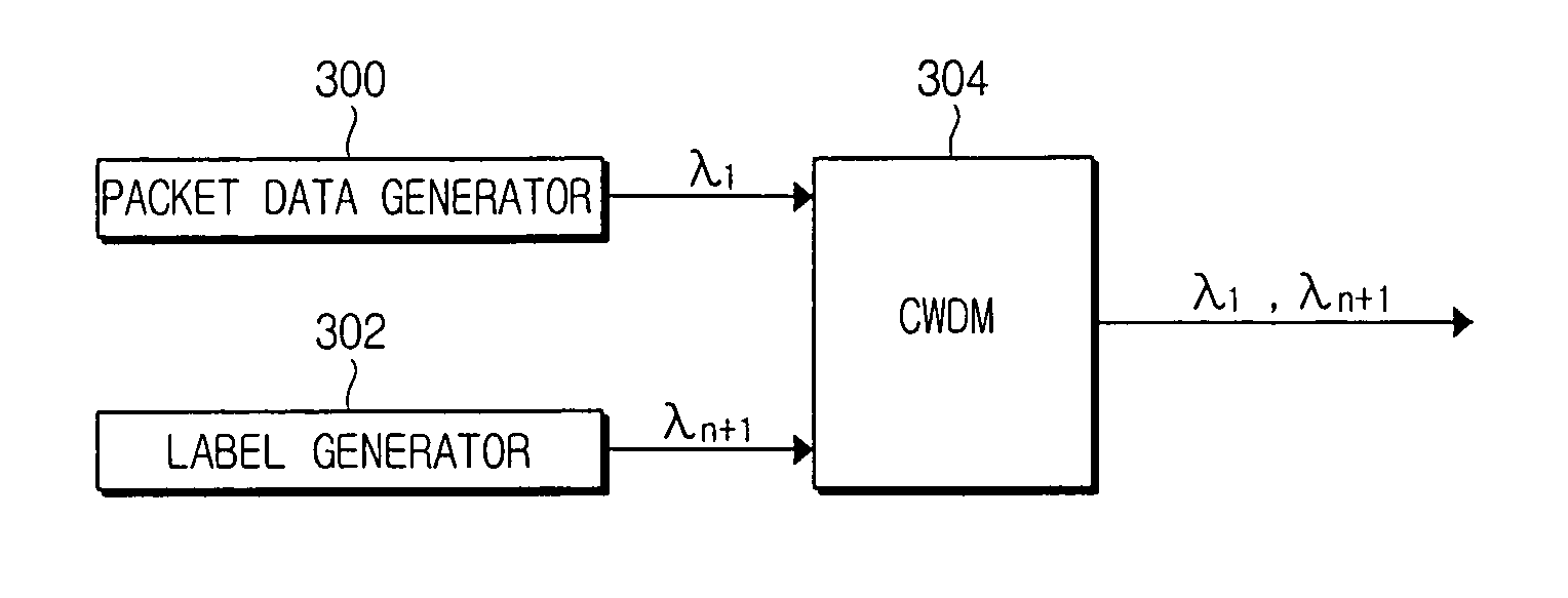
[0022] Hereinafter, an apparatus and method for effectively transmitting a packet data and a label in an optical packet switching network according to an embodiment of the present invention will now be described in detail.

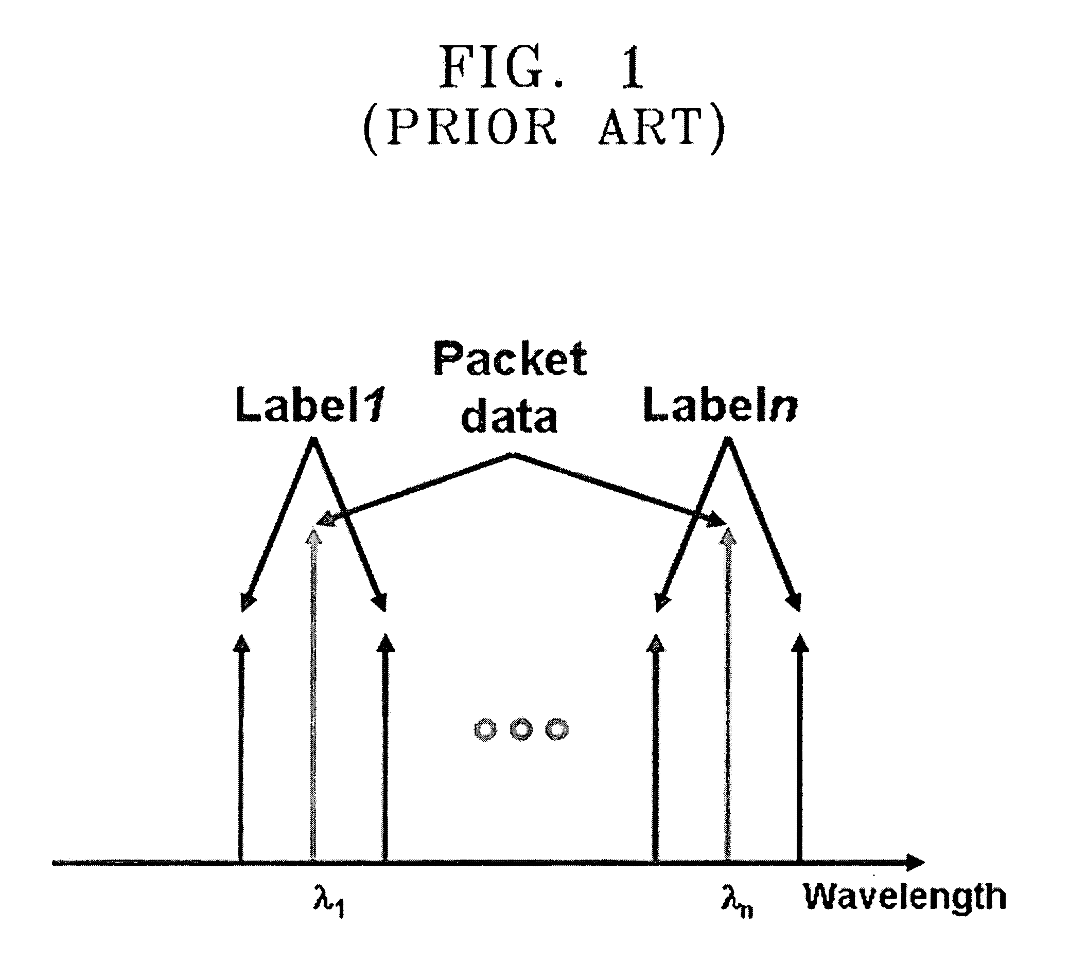
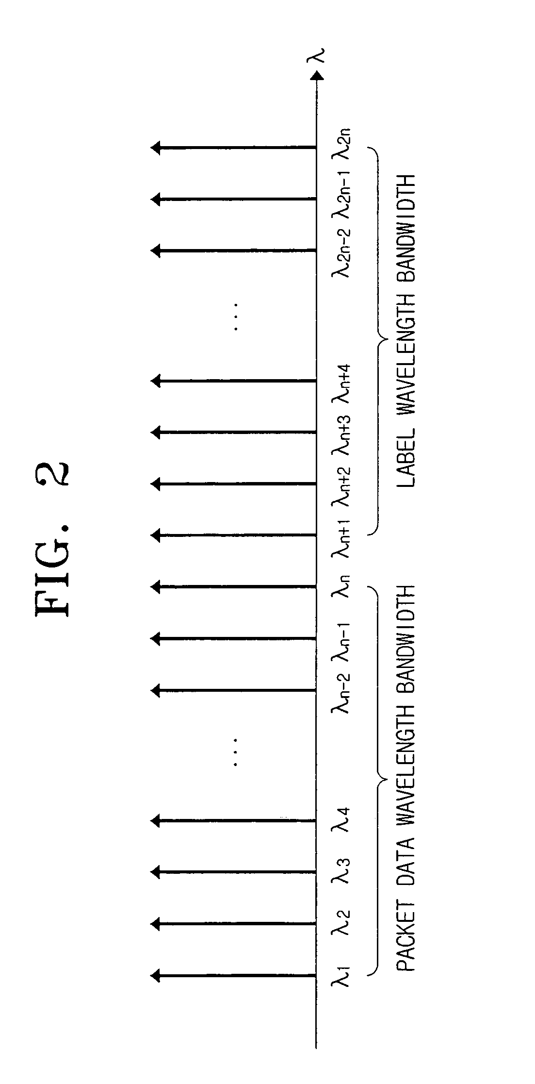
[0023]FIG. 2 illustrates a wavelength bandwidth to transmit packet data and a wavelength bandwidth to transmit a label. The label is control data that encompasses path information about packet data. Referring to FIG. 2, the wavelength bandwidth to transmit the packet data is from λ1 to λn, whereas the wavelength bandwidth to transmit the label is from λn+1 to λ2n. The wavelength to transmit the packet data and the wavelength to transmit the label about the packet data has a constant wavelength difference λn from each other. ‘n’ varies according to a user's setting. According to a conventional wavelength division multiplexing (WDM), a wavelength to transmit packet data and a wavelength to transmit a label about the packet data are neighbored to each other. If the w...


PUM


Abstract

An apparatus and method for effectively transmitting a packet data and a control data of path information about the packet data in an optical packet data switching network. The method includes grouping a plurality of wavelengths into at least two wavelength bandwidths, each wavelength bandwidth being composed of neighboring wavelengths, and transmitting the optical packet data and the control data with wavelengths of different wavelength bandwidths respectively. Since the wavelength to transmit the optical packet data and the wavelength to transmit the control data has a difference from each other, a node receiving optical data easily divides the packet data and the control data.

Description

CROSS REFERENCE TO RELATED APPLICATION [0001] This application claims the benefit of Korean Patent Application No. 2004-88650, filed on Nov. 3, 2004, in the Korean Intellectual Property Office, the entire contents of which are incorporated herein by reference. BACKGROUND OF THE INVENTION [0002] 1. Field of the Invention [0003] The present invention relates to an optical packet data switching network. More particularly, the present invention relates to an apparatus and method for transmitting packet data and labels without error in an optical packet data switching network. [0004] 2. Description of the Related Art [0005] A general optical packet data switching network is composed of a source node where a sender is located, a relay node where a sender and a receiver are located, and a destination node where a receiver is located. Optical signals generated at the source node are transmitted to the destination node through the relay node or directly transmitted to the destination node. [...

Claims


Application Information

Patent Timeline
IPC IPC(8): H04B10/08H04B10/27H04B10/524H04J14/00H04J14/02
CPCH04Q11/0005H04Q11/0066H04Q2011/0039H04Q2011/0069H04B10/25H04B10/27
Inventor PARK, KEUN-JOOKIM, HYUN-CHINSEO, YOUNG-KWANGYOUN, CHUN-JURHEE, JUNE-KOO
Owner SAMSUNG ELECTRONICS CO LTD
Why Eureka
Try Eureka