Communication system using multi-user multiple input multiple output (mu-mimo) communication scheme

Active Publication Date: 2010-06-17
ELECTRONICS & TELECOMM RES INST
View PDF6 Cites 8 Cited by
  • Summary
  • Abstract
  • Description
  • Claims
  • Application Information

AI Technical Summary

Benefits of technology

[0014]According to embodiments of the present invention, it is possible to effectively transmit data to a plurality of users at the sam

Problems solved by technology

Accordingly, when different terminals receive data using the same precoding vector, a dat

Method used


Image

  • Communication system using multi-user multiple input multiple output (mu-mimo) communication scheme
  • Communication system using multi-user multiple input multiple output (mu-mimo) communication scheme
  • Communication system using multi-user multiple input multiple output (mu-mimo) communication scheme

Examples


Example

[0022]Reference will now be made in detail to exemplary embodiments of the present invention, examples of which are illustrated in the accompanying drawings, wherein like reference numerals refer to the like elements throughout. Exemplary embodiments are described below to explain the present invention by referring to the figures.

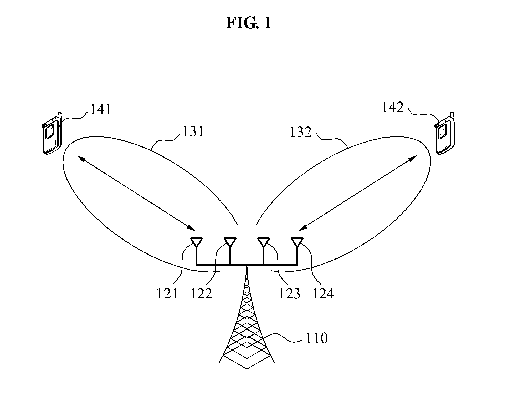
[0023]FIG. 1 is a diagram illustrating a concept of a Multi-user Multiple Input Multiple

[0024]Output (MU-MIMO) communication system according to an embodiment of the present invention.

[0025]A base station 110 may transmit data to terminals 141 and 142 or receive data from the terminals 141 and 142 using a plurality of antennas 121, 122, 123, and 124. The base station 110 may concentrate on transmitting or receiving the data into a particular direction using the plurality of antennas 121, 122, 123, and 124, and a precoding vector. Since an effect of interference against other directions decreases, a data rate at the base station 110 may be enhanced.

[0026]In ...


PUM


Abstract

Provided is a multi-user Multiple Input Multiple Output (MU-MIMO) communication scheme.
A terminal may select a precoding vector from column vectors included in a precoding matrix, and feed back information associated with the selected precoding vector to a base station. The base station may transmit data to the terminal using the precoding vector.

Description

CROSS-REFERENCE TO RELATED APPLICATION[0001]This application claims the benefit of Korean Patent Application No. 10-2008-0126341, filed on Dec. 12, 2008 and Korean Patent Application No. 10-2009-0116554, filed on Nov. 30, 2009 in the Korean Intellectual Property Office, the disclosure of which is incorporated herein by reference.BACKGROUND[0002]1. Field of the Invention[0003]Embodiments of the present invention relate to a multi-user Multiple Input Multiple Output (MU-MIMO) communication scheme.[0004]2. Description of the Related Art[0005]A wireless communication system uses a multi-antenna Multiple Input Multiple Output (MIMO) communication scheme to enhance a frequency efficiency of radio resources. For example, the multi-antenna MIMO communication scheme may use a codebook-based multi-antenna MIMO communication scheme.[0006]In the codebook-based multi-antenna MIMO communication, a terminal may select, as a precoding vector, at least one column vector from a plurality of column ve...

Claims


Application Information

Patent Timeline
IPC IPC(8): H04B1/38H04L27/28H04M1/00
CPCH04B7/0417H04B7/0452H04B7/0658H04B7/0639H04B7/0632H04B7/0626
Inventor SEO, BANGWONKO, YOUNG JOAHN, JAE YOUNG
Owner ELECTRONICS & TELECOMM RES INST
Why Eureka
Try Eureka