Spark ignition system with diagnostic capabilities

Inactive Publication Date: 2005-05-05
FEDERAL MOGUL WORLD WIDE
View PDF41 Cites 0 Cited by
  • Summary
  • Abstract
  • Description
  • Claims
  • Application Information

AI Technical Summary

Benefits of technology

[0013] According to another embodiment of the invention, the flexor joint comprises a conductive sleeve which is operatively disposed within the longitudinal bore and slideably receives each of the lead and center wires and the respective upper and lower ends thereof. The sleeve has a plurality of opposing upper tangs near its upper end which are resiliently biased toward the lead wire so that the upper tangs exert substantially balanced opposing forces upon the lead wire. Similarly, the sleeve has a plurality of opposing lower tangs adjacent its lower end which are resiliently biased toward the center wire such that the lower tangs exert substantially balanced opposing forces upon the center wire. In this manner, the conductive sl

Problems solved by technology

In coil-on-plug applications, high levels of vibration can cause the connection between the high voltage coil terminal and the spark plug terminal electrode to become non-continuous and intermittent.
Though an intermittent contact does not usually prevent a higher voltage ignition pulse from transmitting through to the spark plug (as these pulses usually have a voltage ranges from 5,000 volts to 40,000 volts typically and are thus capable of bridging most small distance gaps), it can present certain problems when low voltage diagnostics are involved.
Prior art connections between the coil lead wire and the spark plug center electrode include too much flexibility and inherent resiliency to achieve reliably continuous contact during high vibration situations.
An intermittent connection between the ignition coil high voltage output terminal and the spark plug terminal electrode can also

Method used


Image

  • Spark ignition system with diagnostic capabilities
  • Spark ignition system with diagnostic capabilities
  • Spark ignition system with diagnostic capabilities

Examples


Example

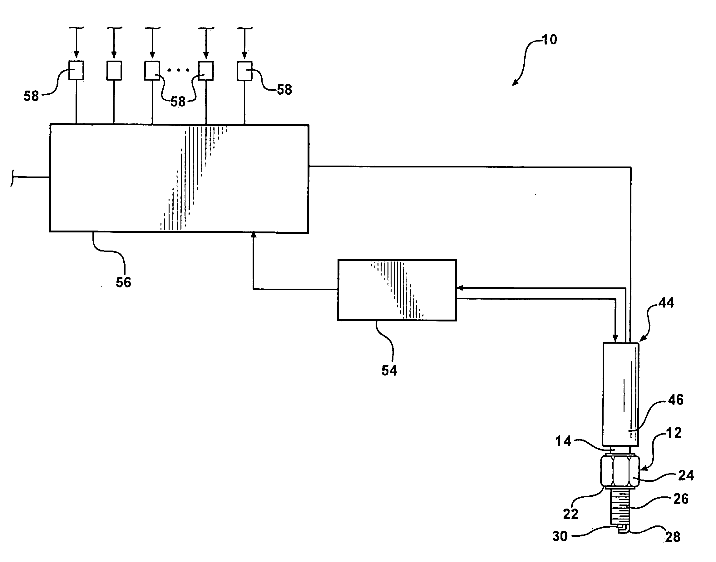
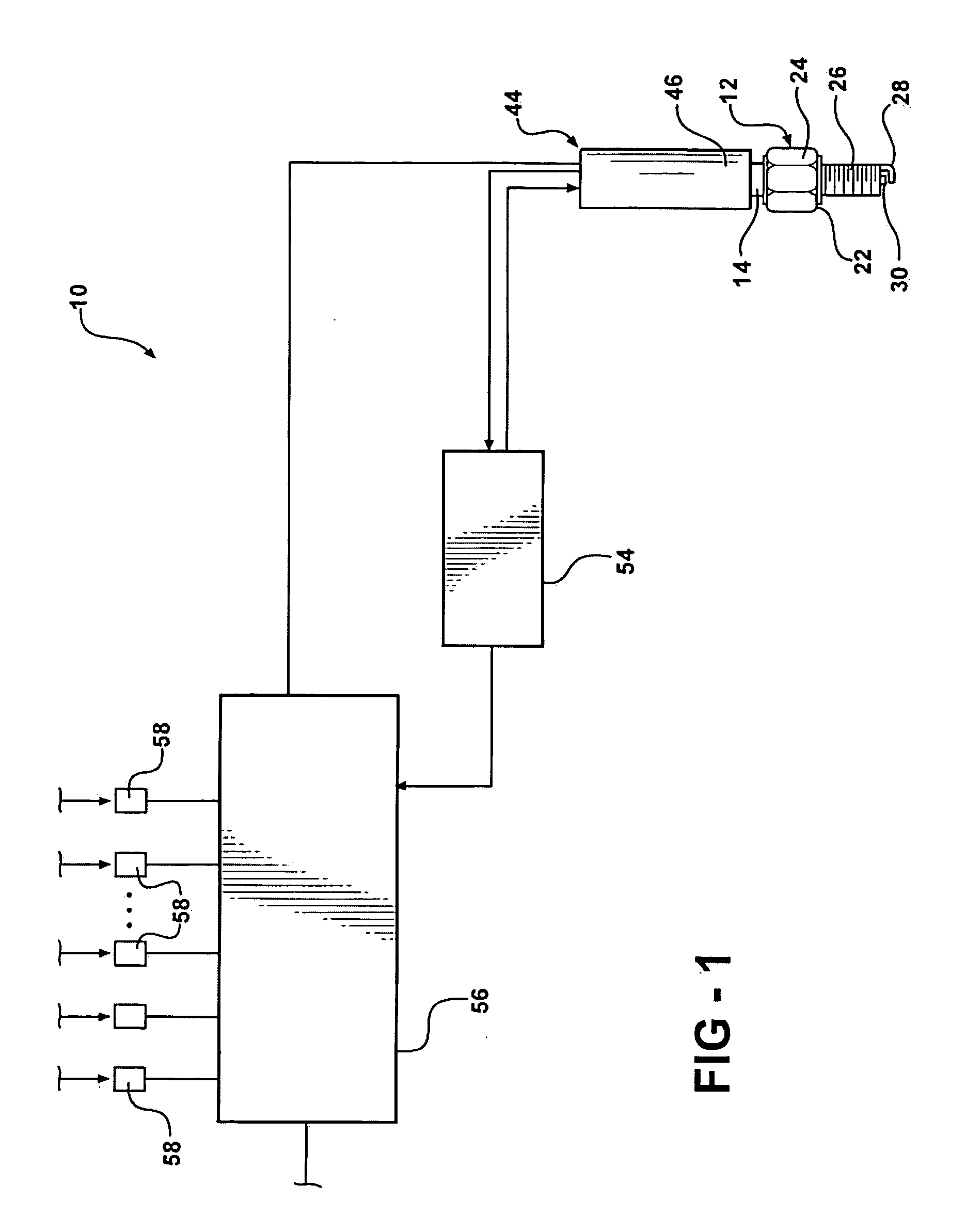
[0024] Referring to the figures, wherein like numerals indicate like or corresponding parts throughout the several views, a sparking ignition system with diagnostic capabilities for an internal combustion engine controlled by a computer control module is generally shown at 10 in FIG. 1. The system 10 includes a sparking device, generally indicated at 12, which, in the preferred embodiment, comprises a spark plug. However, the sparking device 12 may include igniters and other such ignition devices for creating a timed spark in the combustion chamber (or a pre-chamber) of an internal combustion engine.

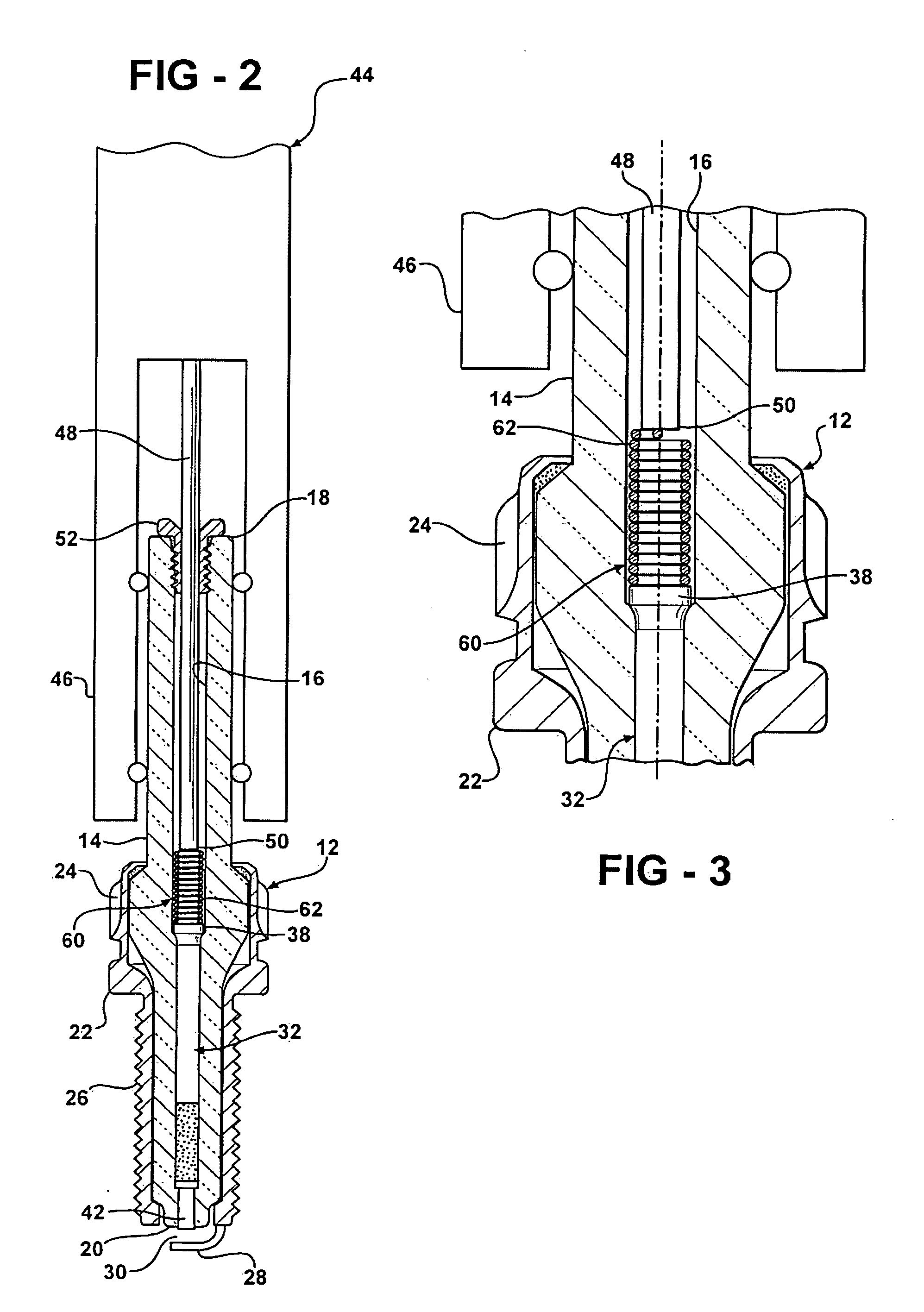
[0025] As shown in FIGS. 2 and 4, the sparking device 12 includes an electrical insulator 14 typically made of a ceramic material. The insulator 14 includes an internal longitudinal bore 16 which passes fully from an upper end 18 of the insulator 14 to a lower end 20. A shell 22, typically fabricated from steel encases the lower half of the insulator 14 and is provided with a tool grip ...


PUM


Abstract

An ignition and diagnostic system (10) for an internal combustion engine includes a sparking device (12) through which a low voltage diagnostic device (54) monitors a sensing feature, for example spark gap (30) conditions, during spark intervals and returns diagnostic feedback to an engine control module (56). A coil (44) is electrically operatively connected to the sparking device (12) through a lead wire (48). The lead wire (48) can be removed and reinstalled with respect to the sparking device (12) via a flexor joint (60) for installation and maintenance. The flexor joint (60) enables positive electrical contact during operation so that low voltage signals from the diagnostic device (54) are maintained even during severe vibration conditions. The flexor joint (60) comprises in one embodiment a compression spring (62) which is fully compressed or over-compressed. In another embodiment, the flexor joint (60) comprises a tubular sleeve (64, 64′) having cantilevered upper tangs (70, 70′) which resiliently engage the lead wire (48), and lower tangs (76) which similarly engage the center wire (32) of the sparking device (12) in a resilient manner.

Description

[0001] This invention claims priority to U.S. Provisional Application No. 60 / 517540 filed Nov. 5, 2003.BACKGROUND OF THE INVENTION [0002] 1. Field of the Invention [0003] The present invention relates generally to spark plugs, igniters, and other such ignition devices and to techniques for connecting an incoming terminal contact to the center electrode assembly of the ignition device. More particularly, the invention relates to a terminal end connection specifically designed to provide a continuous, uninterrupted electrical connection with an ignition lead or ignition coil high-voltage terminal so that the spark gap or other sensor diagnostic feature can be conducted at low voltages in the interval between sparks. [0004] 2. Related Art [0005] Numerous types of connections have been used for electrically coupling an ignition lead to the terminal end of a spark plug. Their particular construction depends largely upon the specific application for which they are used. For instance, some...

Claims


Application Information

Patent Timeline
IPC IPC(8): F02P17/00F02P17/04F02P17/12
CPCF02P17/04F02P2017/121F02P17/12
Inventor MCMURRAY, MARK S.LYKOWSKI, JAMES D.
Owner FEDERAL MOGUL WORLD WIDE
Why Eureka
Try Eureka