
Recessed Light Apparatus

Active Publication Date: 2017-08-31
WU LIANGJU
View PDF1 Cites 7 Cited by
  • Summary
  • Abstract
  • Description
  • Claims
  • Application Information

AI Technical Summary

Benefits of technology

The invention is a recessed light apparatus with several advantages. First, it includes a heat sink with a light source unit mounted at its bottom, allowing for efficient heat transfer. Second, the heat sink has a detachable extension portion with a threaded structure, ensuring effective heat transmission. Third, the heat sink has a heat conducting slot and an installing portion tightly contacted via the heat conducting slot for fast heat transmission. Fourth, the heat sink is made of solid material with high thermal conductivity. Fifth, a heat conductive element is included to transfer heat from the light source unit to the heat sink, reducing heat accumulation and prolonging the light source unit's lifespan. Lastly, a first thermal expansion member self-expands to block a heat conducting channel to prevent flame or fire spreading in case of fire.

Problems solved by technology

Since the recessed light fixture is installed into the ceiling, the ceiling structure will be damaged.
In other words, the ceiling panel, especially the fireproof ceiling panel, will be damaged by forming the installing opening and mounting the recessed light fixture thereat.
Therefore, the damaged ceiling panel will lose or reduce its fireproof capability.
When the recessed light fixture is installed to couple at the beam structure as a support, the strength of the beam structure will be weakened.
Once the beam structure is damaged or burnt, the beam structure will lose its supporting ability and the ceiling will be collapsed.

Method used


Image

  • Recessed Light Apparatus
  • Recessed Light Apparatus
  • Recessed Light Apparatus

Examples


Embodiment Construction

[0048]The following description is disclosed to enable any person skilled in the art to make and use the present invention. Preferred embodiments are provided in the following description only as examples and modifications will be apparent to those skilled in the art. The general principles defined in the following description would be applied to other embodiments, alternatives, modifications, equivalents, and applications without departing from the spirit and scope of the present invention.

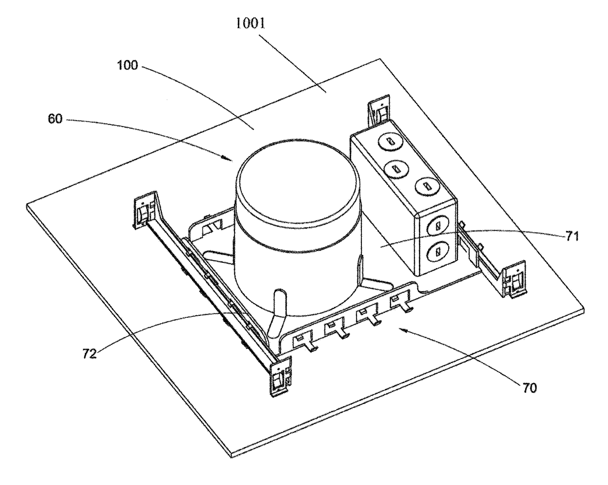
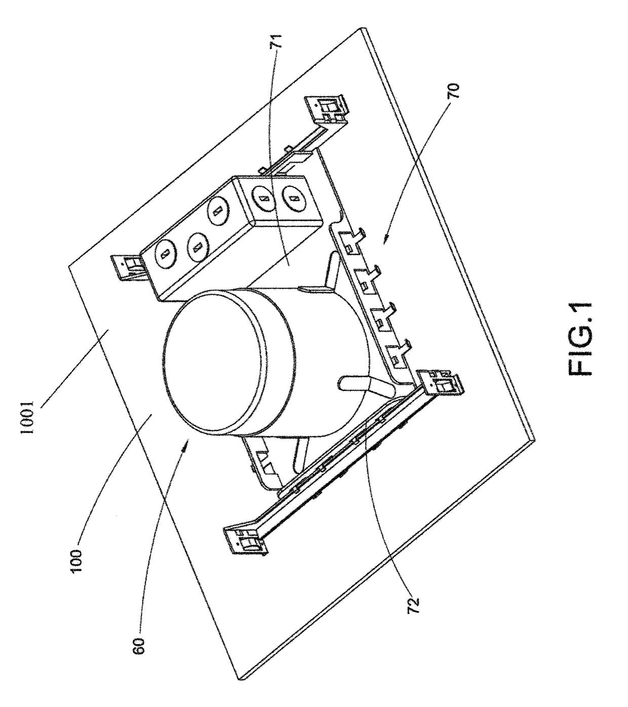
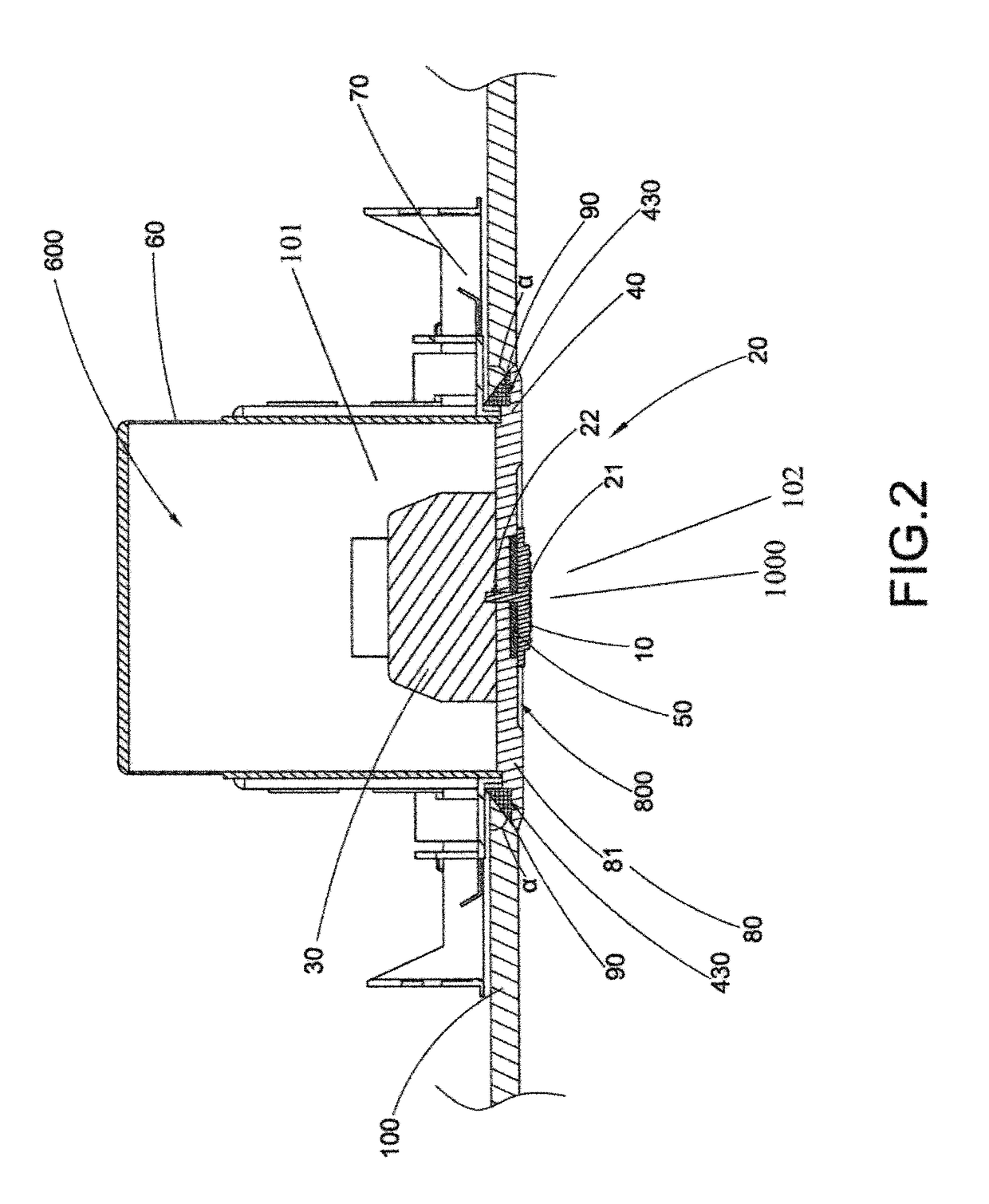
[0049]Referring to FIGS. 1 to 5B of the drawings, a recessed light apparatus according to a first preferred embodiment of the present invention is illustrated, wherein the ceiling light apparatus, such as a recessed light apparatus, comprises a light source unit 10, at least a heat conductive element 20, and at least a heat sink 30. The light source unit 10 is arranged for electrically connected to an external power source for operation. The heat conductive element 20 is extended from the light s...


PUM


Abstract

A recessed light apparatus for being installed at a ceiling includes a light source unit, a heat sink for dissipating heat generated from the light source unit, and a thermal insulating member coupled between the heat sink and the light source unit to define an upper space above the heat insulating member and a bottom space below the thermal insulating member. In case of fire, the heat insulating member prevents flame or fire spreading from the bottom space to the upper space.

Description

CROSS REFERENCE OF RELATED APPLICATION[0001]This is a Continuation application that claims the benefit of priority under 35 U.S.C. §120 to a non-provisional application, application Ser. No. 14 / 787,267, filed Oct. 26, 2015, which is a non-provisional application that claims priority to PCT application, international application number PCT / CN2013 / 090053, international filing date Dec. 20, 2013, which claims priority to Chinese application, application number CN103363408 Å, and filing date Apr. 26, 2013.NOTICE OF COPYRIGHT[0002]A portion of the disclosure of this patent document contains material which is subject to copyright protection. The copyright owner has no objection to any reproduction by anyone of the patent disclosure, as it appears in the United States Patent and Trademark Office patent files or records, but otherwise reserves all copyright rights whatsoever.BACKGROUND OF THE PRESENT INVENTION[0003]Field of Invention[0004]The present invention relates to a lighting fixture,...

Claims


Application Information

Patent Timeline
IPC IPC(8): F21V25/12F21V21/04F21S8/02F21V29/76
CPCF21V25/125F21V29/763F21V21/04F21Y2105/18F21Y2115/15F21Y2115/10F21S8/026F21V29/773
Inventor WU, LIANGJU
Owner WU LIANGJU
Learn More