Prosthetic device, method of planning bone removal for implantation of prosthetic device, and robotic system

a prosthetic device and robotic system technology, applied in the field of prosthetic devices for implantation, can solve the problems of unfavorable movement of the prosthetic device relative to the bone, less than fully constrained prosthetic device, and unwanted movement of the tibial inlay

Active Publication Date: 2014-07-03
MAKO SURGICAL CORP
View PDF2 Cites 23 Cited by
  • Summary
  • Abstract
  • Description
  • Claims
  • Application Information

AI Technical Summary

Problems solved by technology

Using the conventional techniques, undesired movement of the prosthetic device relative to the bone may occur.
This expansion gap may cause the prosthetic device to be less than fully constrained, which can permit unwanted movement of the prosthetic device.
For example, during trial articulation of a leg, contact forces from a femoral condyle can cause unwanted movement of a tibial inlay.
In addition, undesired movement can occur during final fixation as a surgeon presses against the prosthetic device to disperse the bone cement and squeeze out excess bone cement.
Using conventional techniques, it also may be undesirably difficult to properly position a prosthetic device in the pocket in the bone.
For example, there can be difficulty in positioning the cup of a hip acetabulum in a desired tilt / abduction and anteversion due to difficulty in knowing exactly where a pelvis is located during total hip arthroplasty.

Method used


Image

  • Prosthetic device, method of planning bone removal for implantation of prosthetic device, and robotic system
  • Prosthetic device, method of planning bone removal for implantation of prosthetic device, and robotic system
  • Prosthetic device, method of planning bone removal for implantation of prosthetic device, and robotic system

Examples


Embodiment Construction

[0080]Presently preferred embodiments of the invention are illustrated in the drawings. An effort has been made to use the same or like reference numbers throughout the drawings to refer to the same or like parts.

Overview

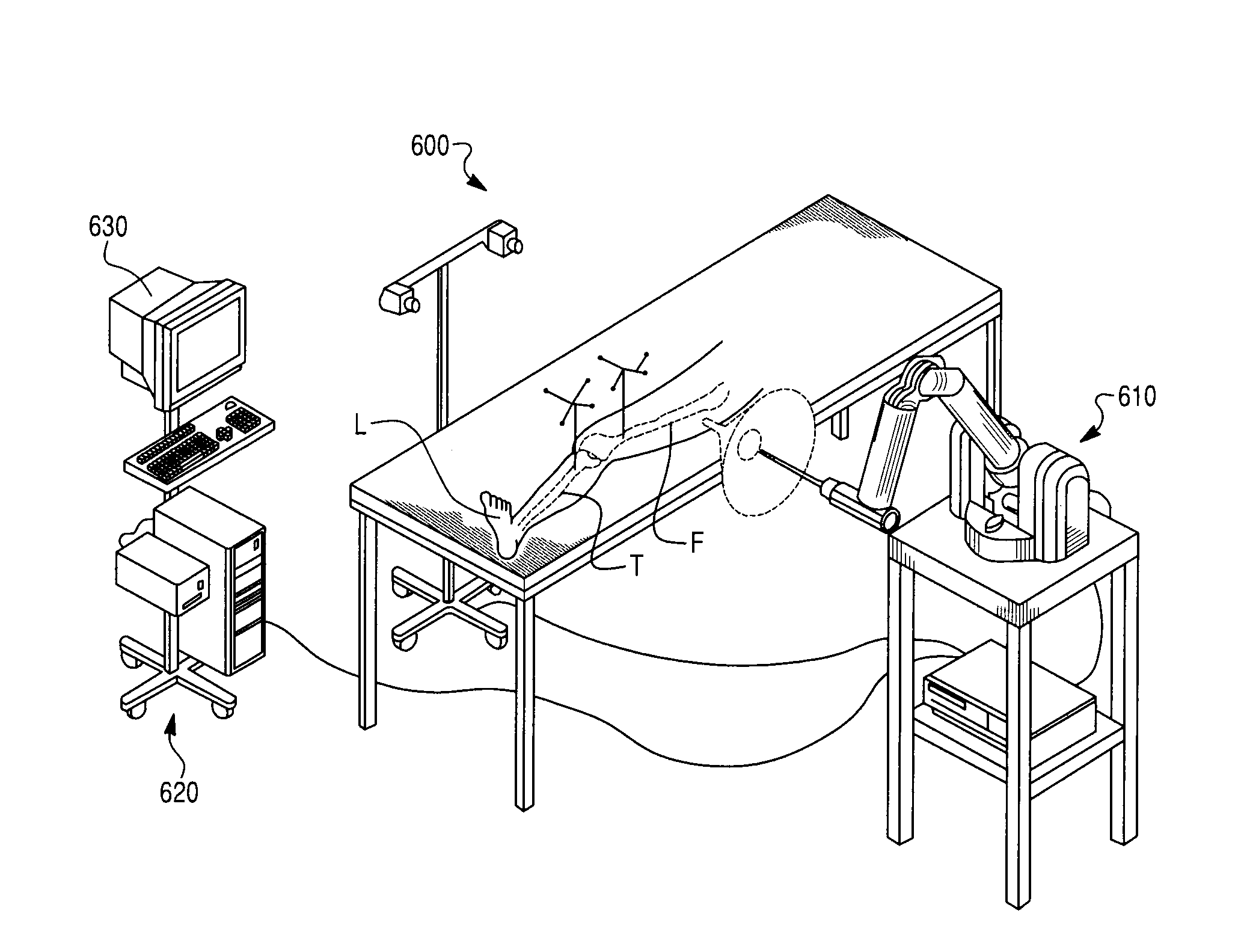
[0081]The preferred embodiments relate, in general, to methods for planning bone removal to allow implantation of a prosthetic device to create a constraining relationship between the bone and the prosthetic device. The preferred embodiments also relate to prosthetic devices that are configured to achieve such a constraining relationship and a robotic system that can be used to facilitate the creation of such a constraining relationship.

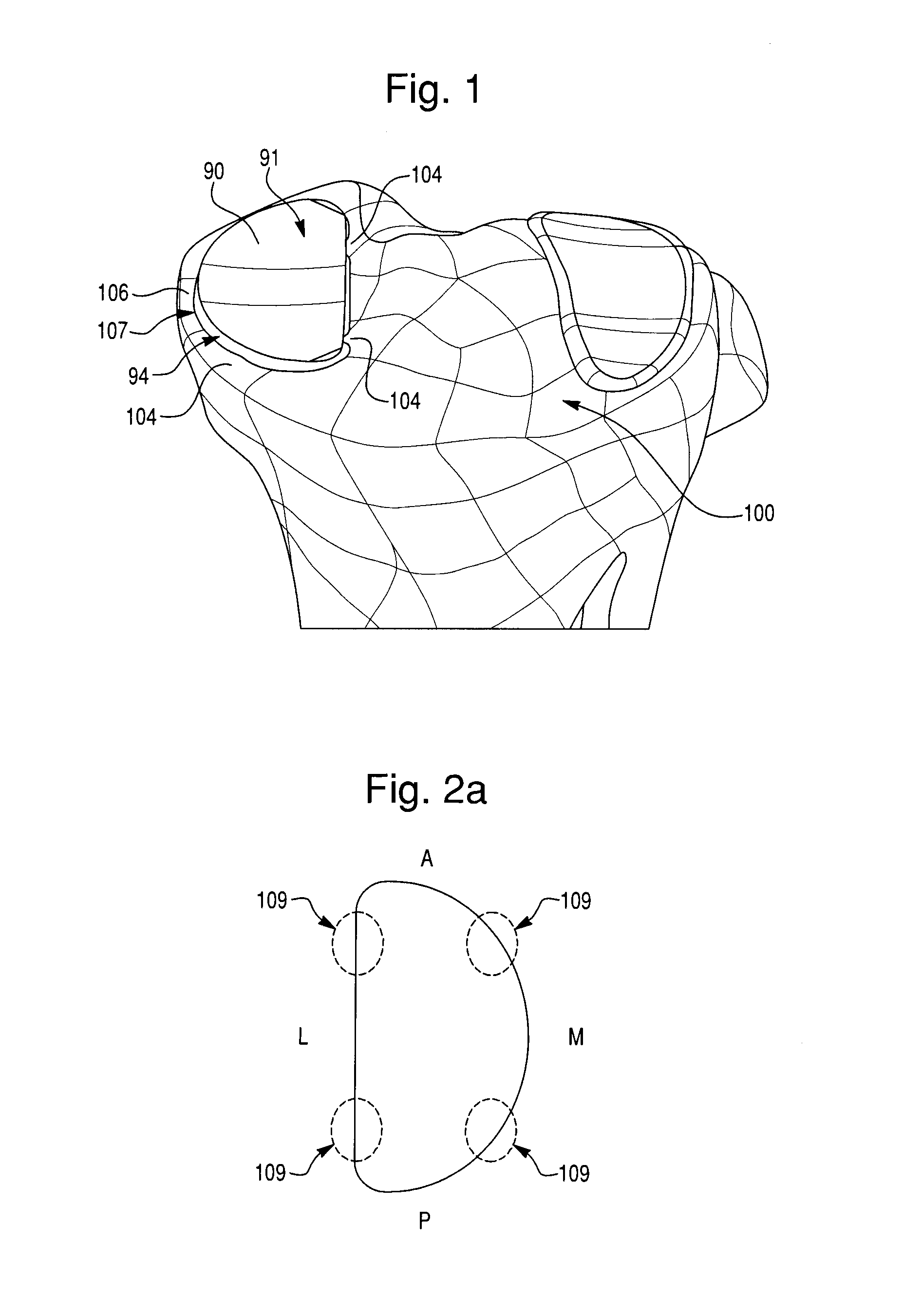
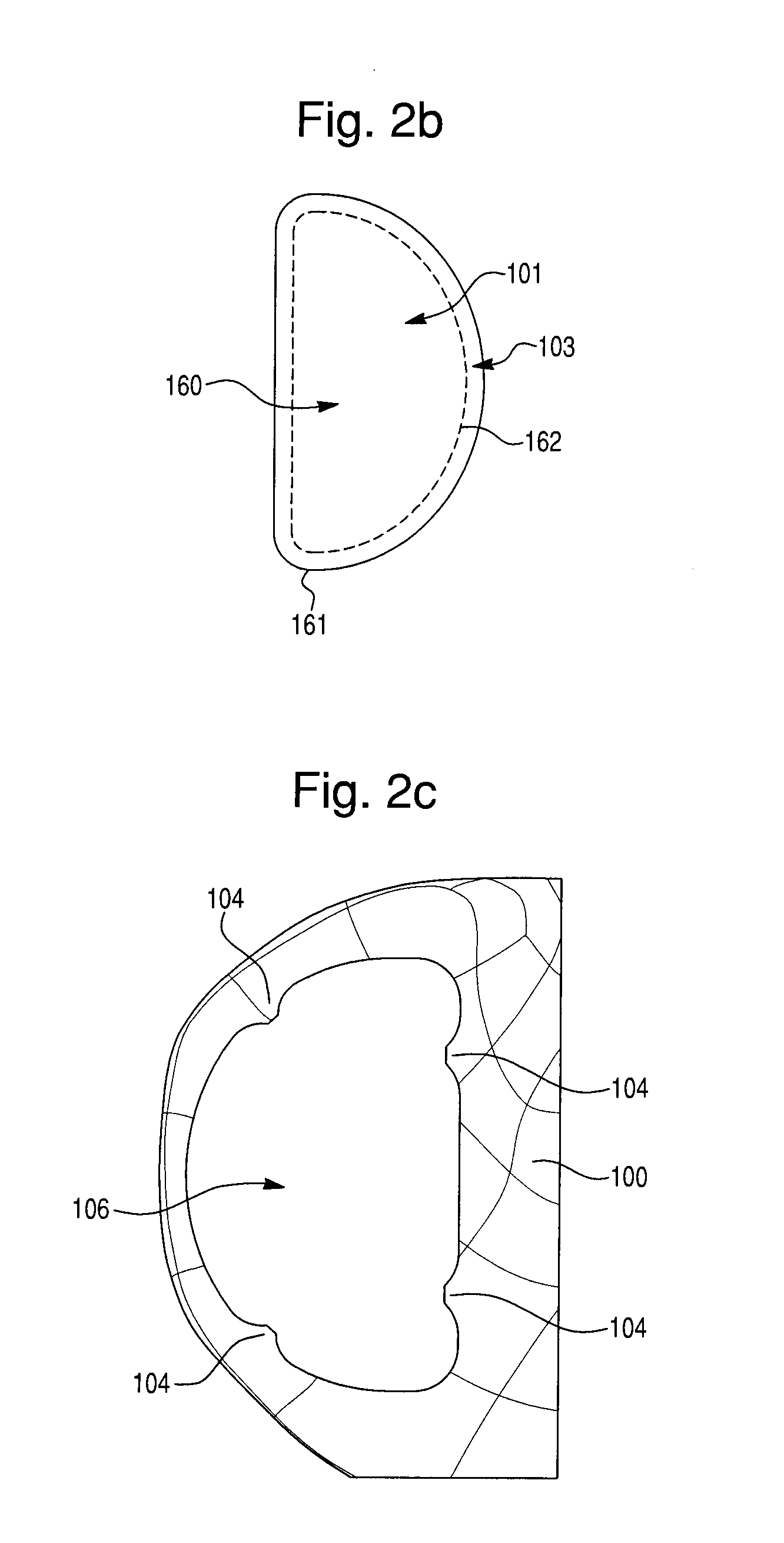
[0082]In general, the methods for planning include storing data representative of the prosthetic device in a computer readable medium. The methods further include defining, based on the data, at least one bone-cutting pattern for (i) removing a first portion of bone in a first area sufficient to seat a body portion of the prosthetic ...


PUM


Abstract

A robotic system for preparing a bone to receive a prosthetic device. The robotic system includes a controllable guide structure configured to guide cutting of the bone into a shape for receiving the prosthetic device, and a computer readable medium for storing data representative of the prosthetic device. The prosthetic device includes a body portion having an implantation surface configured to face the bone upon implantation and at least one feature that provides a constraint structure that will constrain the prosthetic device in the bone. The robotic system includes a control system for controlling the guide structure, and is configured to define at least one bone-cutting pattern for (i) removing a first portion of bone in a first area sufficient to seat the body portion and (ii) at least one of removing and maintaining a second portion of bone in a second area configured to interact with the constraint structure.

Description

CROSS-REFERENCE TO RELATED PATENT APPLICATIONS[0001]This application is a divisional of application Ser. No. 12 / 711,137, filed on Feb. 23, 2010, which claims the benefit of Provisional Application No. 61 / 208,451, filed on Feb. 24, 2009, both of which are hereby incorporated by reference in their entireties.BACKGROUND OF THE INVENTION[0002]1. Field of Invention[0003]The present invention relates to a prosthetic device for implantation in bone, methods of planning bone removal for implantation of a prosthetic device in bone, and robotic systems for preparing a bone to receive a prosthetic device.[0004]2. Description of Related Art[0005]Conventional prosthetic implantation techniques involve resecting a pocket of material from a bone to provide a void or pocket within the bone that receives a prosthetic device. After resection of bone material is complete, the prosthetic device is implanted within the pocket. The prosthetic device is typically secured in place with bone cement.[0006]Us...

Claims


Application Information

Patent Timeline
Patent Type & Authority Applications(United States)
IPC IPC(8): A61B19/00
CPCA61B19/56A61B19/2203A61B17/1746A61B17/175A61B17/1764A61F2/30724A61F2/30771A61F2/36A61F2/38A61F2002/30795A61F2002/30805A61F2002/30823A61F2002/30878A61F2002/30883A61F2002/3412A61F2002/3895A61F2002/4631A61B34/30A61B90/39A61B34/25
Inventor NORTMAN, SCOTT DAVIDMISTRY, AMITOTTO, JASON K.VORHIS, ROBERT VANNADZADI, MARK ELLSWORTHJAMIESON, MIRANDA
Owner MAKO SURGICAL CORP
Why Eureka
Try Eureka