Humeral component of a shoulder prosthesis

a technology of humeral components and shoulder prosthesis, which is applied in the field of modular shoulder arthroplasty system to achieve the effect of widening

Active Publication Date: 2014-07-03
ARTHREX INC
View PDF0 Cites 46 Cited by
  • Summary
  • Abstract
  • Description
  • Claims
  • Application Information

AI Technical Summary

Benefits of technology

The patent text describes a mechanism for positioning a stem module and a joint adapter in a way that they cannot move in relation to each other. This is achieved through the use of protrusions and recesses on the stem module and joint adapter that prevent movement in the inclination angle of the stem module, allowing for positioning in discrete steps. Additionally, the text also describes the use of a ball screw for fastening the joint adapter to the stem module, which allows for continuous positioning of the stem module and joint adapter. The patent results in improved precision and stability in positioning equipment.

Problems solved by technology

Another problem to be solved is to further improve adaption of the prosthesis to optimize the range of motion.

Method used


Image

  • Humeral component of a shoulder prosthesis
  • Humeral component of a shoulder prosthesis
  • Humeral component of a shoulder prosthesis

Examples


first embodiment

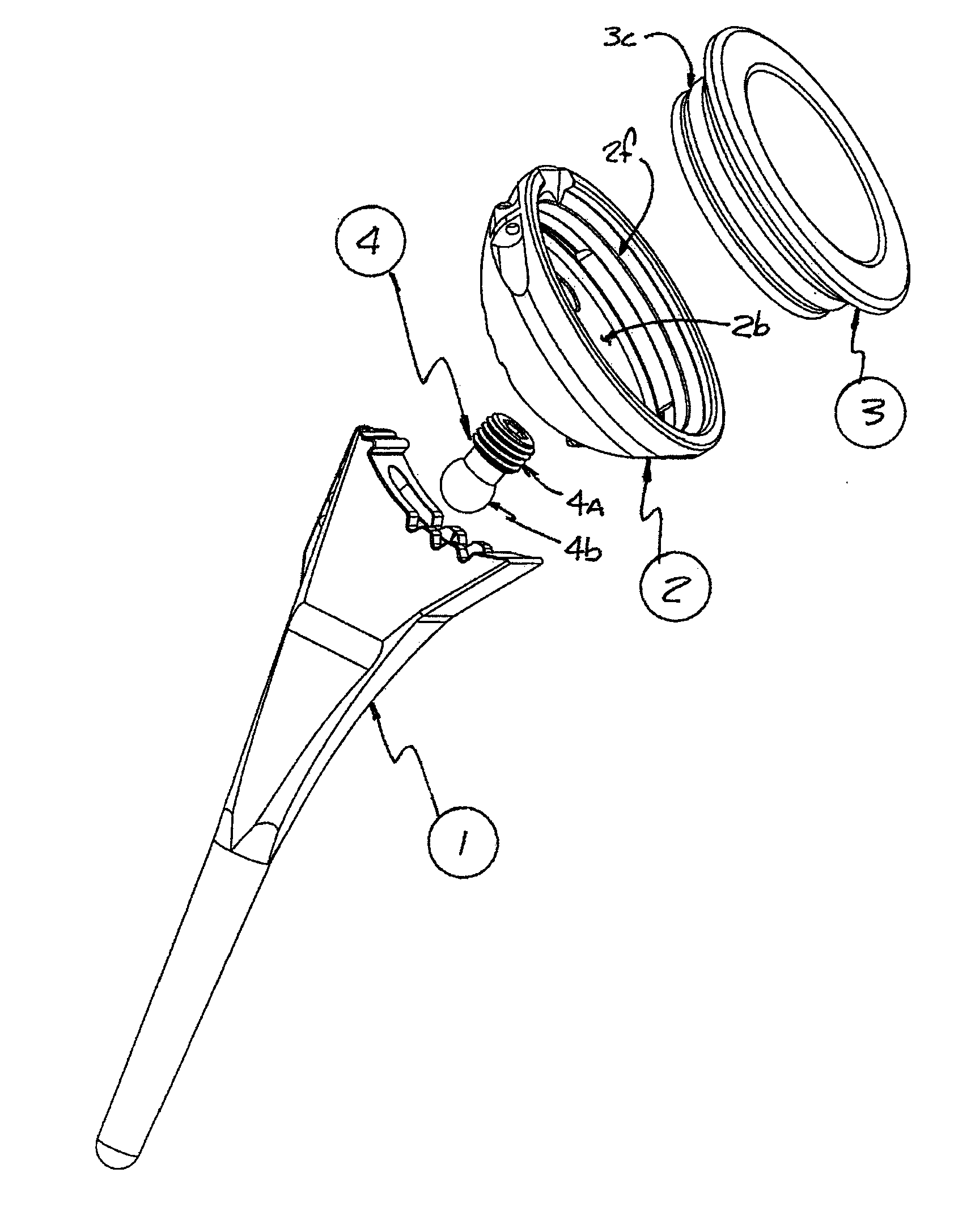
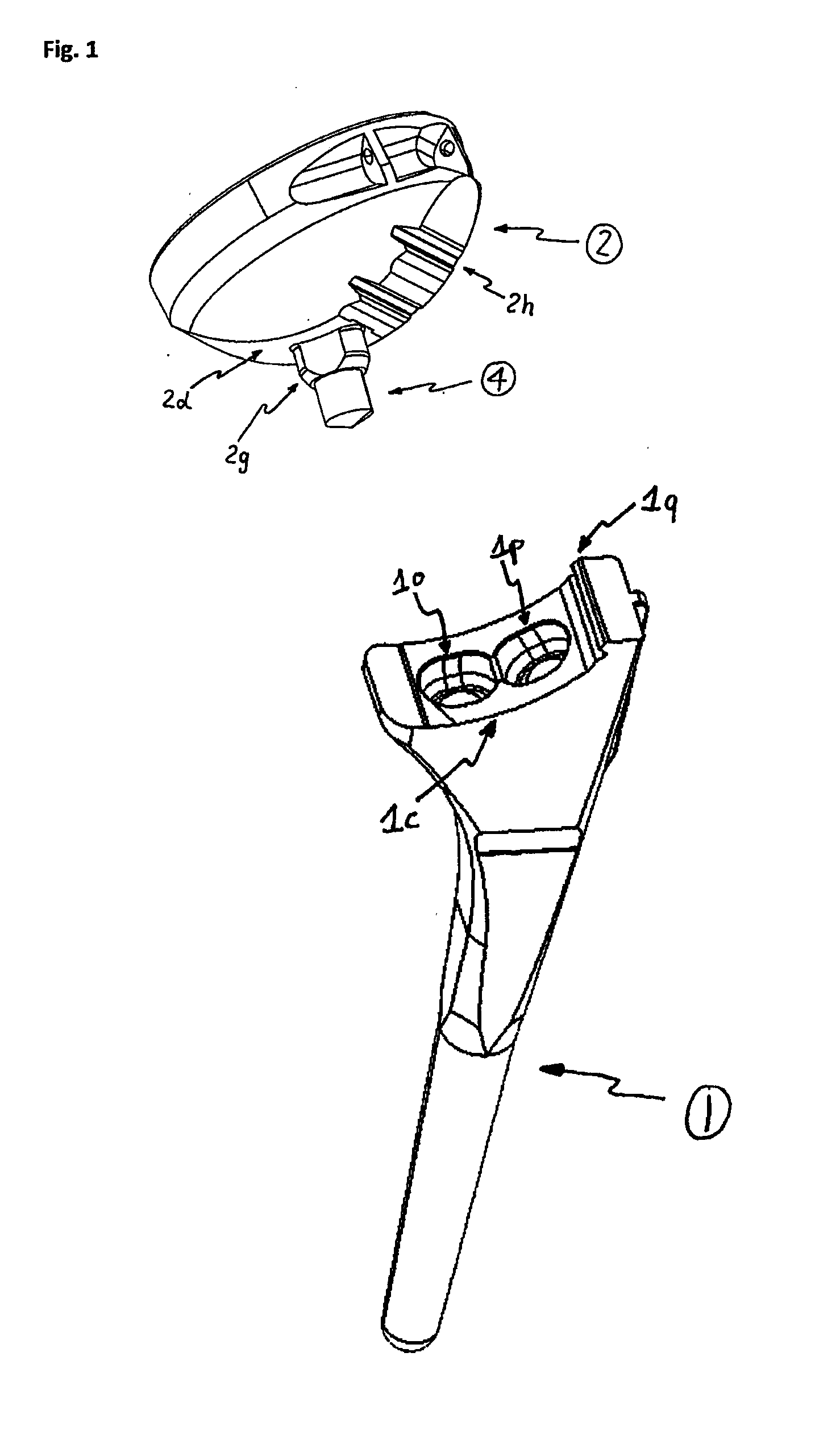
[0048]FIG. 1 shows the humeral component of a shoulder prosthesis. It includes a stem module (1) and a joint adapter (2). The adapter support surface (2d) of joint adapter (2) interfaces with the stem support surface (1c) of stem module (1). Both have radial arc shaped sections. The radial arc shaped sections have sections of a cylinder surface and therefore only allow one kind of rotation around the cylinder axis. Rotation around other axis, specifically around axis perpendicular to the cylinder axis is not possible. The remaining degrees of freedom are rotation around a cylinder axis and there may be a translation parallel to the cylinder axis. A screw (4) through a preferably circular protrusion (2g) of the joint adapter (2) goes into one of the threaded holes (1o, 1p) defining alternate positions and therefore alternate inclination angles between the joint adapter (2) and the stem module (1). The screw (4) fixes the joint adapter to the stem module and locks the joint adapter ag...

second embodiment

[0053]FIGS. 5a and 5b show a joint adapter (2) mounted at different inclination angles to the stem module (1), using the respective hole (2z, 2x) in the joint adapter (2) for the screw (4).

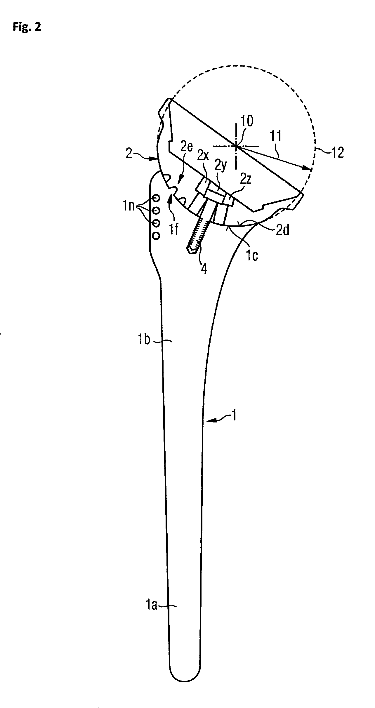
[0054]FIG. 6 shows the definition of the inclination angle 13, also known as neck shaft angle. It is the angle between the longitudinal axis of the stem module (1), which is essentially the longitudinal axis of a bone (for example, humerus) into which the stem is inserted, and the center axis of the joint adapter (2, 6, 7). It may be in a range between 120 and 170 degrees and is preferably between 135 and 155 degrees. This inclination angle may be modified by positioning of the joint adapter (2, 6, 7) against the stem module (1).

[0055]FIG. 7 shows a side view of the stem module in detail. The stem may either be a monobloc configuration or consist of several parts. It has a cylindrical or tapered distal aspect (1a) developing into a larger, polygonal form (1b). The most proximal aspect of the mono...


PUM


Abstract

A humeral component of a shoulder prosthesis encloses a stem module which has a shank and an upper shank portion with a stem support surface. A joint adapter is adapted to hold either a liner or a spherical cap. The joint adapter has an adapter support surface which interfaces with the stem support surface. Further, the stem support surface and the adapter support surface have corresponding radial arc shaped sections which allow positioning of the joint adapter against the stem module at different inclination angles. For fastening the joint adapter to the stem module, a bolt or screw is provided.

Description

CROSS-REFERENCE TO RELATED APPLICATIONS[0001]This is a divisional of U.S. patent application Ser. No. 13 / 346,901, filed on Jan. 10, 2012, now U.S. Pat. No. 8,663,333, which claims the benefit of U.S. Provisional Application No. 61 / 431,606, filed Jan. 11, 2011, the entire disclosure of which is incorporated by reference herein.FIELD OF THE INVENTION[0002]The present invention relates to a modular shoulder arthroplasty system for surgical reconstitution of the shoulder and, in particular, to prosthetic replacement of the humerus.BACKGROUND OF THE INVENTION[0003]The shoulder joint is a ball-and-socket joint which has an exceptional range of motion. Shoulder instability and other maladies of the shoulder joint, such as arthrosis or fracture, may require a replacement of the joint.[0004]A shoulder joint prosthesis which includes the replacement of the convex head of the humerus is disclosed in U.S. Pat. No. 7,819,923. It reflects the orientation and the center of rotation of actual joint...

Claims


Application Information

Patent Timeline
Patent Type & Authority Applications(United States)
IPC IPC(8): A61F2/40
CPCA61F2/4014A61F2/4059A61F2002/30331A61F2002/30387A61F2002/30405A61F2002/30433A61F2002/3054A61F2002/30604A61F2002/4018A61F2002/4022A61F2002/4051A61F2002/4074
Inventor METCALFE, NICK J.T.MICHEL, GERLINDEGUEDERIAN, GREGORY A.HABERMAYER, PETERROMEO, ANTHONY A.KRUPP, STEFANVANDERMEULEN, STEVEN L.GALLEN, KEVIN J.
Owner ARTHREX INC
Why Eureka
Try Eureka