Paper Discharge Mechanism, Printing Device, and Terminal Equipment

Active Publication Date: 2014-07-17
SHANDONG NEW BEIYANG INFORMATION TECH CO LTD
View PDF2 Cites 20 Cited by
  • Summary
  • Abstract
  • Description
  • Claims
  • Application Information

AI Technical Summary

Benefits of technology

[0008]The purpose of the present invention is to provide a paper discharge mechanism capable of preventing a user from interfering with paper

Problems solved by technology

Currently, such self-service terminal equipments with a printing function generally have the following problem: if a user interferes with paper output during a printing process, a printing device fault may be caused, e.g. when a user blocks a paper exit and stops paper output during a printing process, paper jam and stacking are easily caused in an automatic terminal exit and can be hardly observed outside a self-service terminal eq

Method used


Image

  • Paper Discharge Mechanism, Printing Device, and Terminal Equipment
  • Paper Discharge Mechanism, Printing Device, and Terminal Equipment
  • Paper Discharge Mechanism, Printing Device, and Terminal Equipment

Examples


Embodiment Construction

[0069]Embodiments of the present invention will be described in details hereinafter in combination with the accompanying drawings. However, the present invention may be implemented by various different methods limited and covered by the claims.

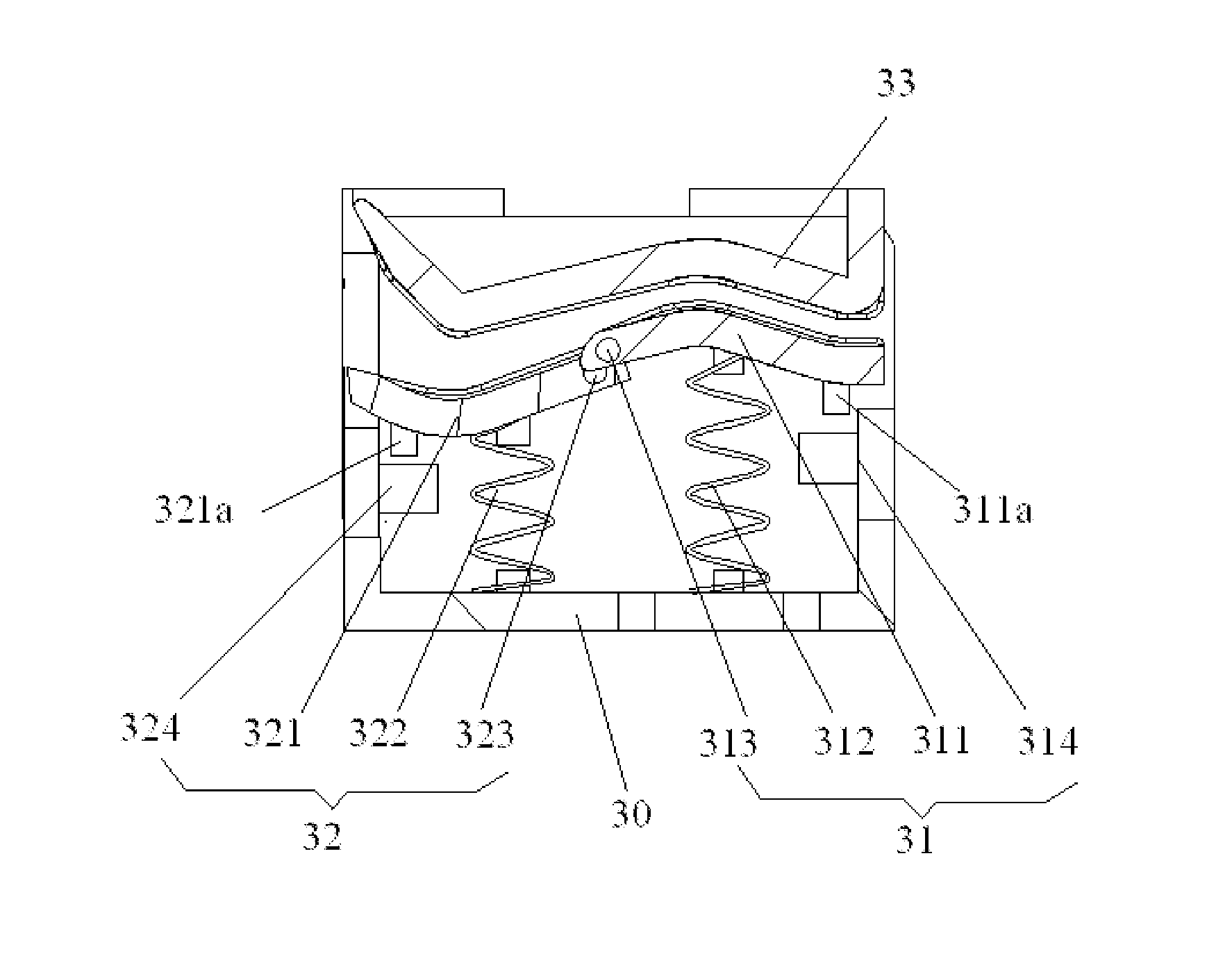
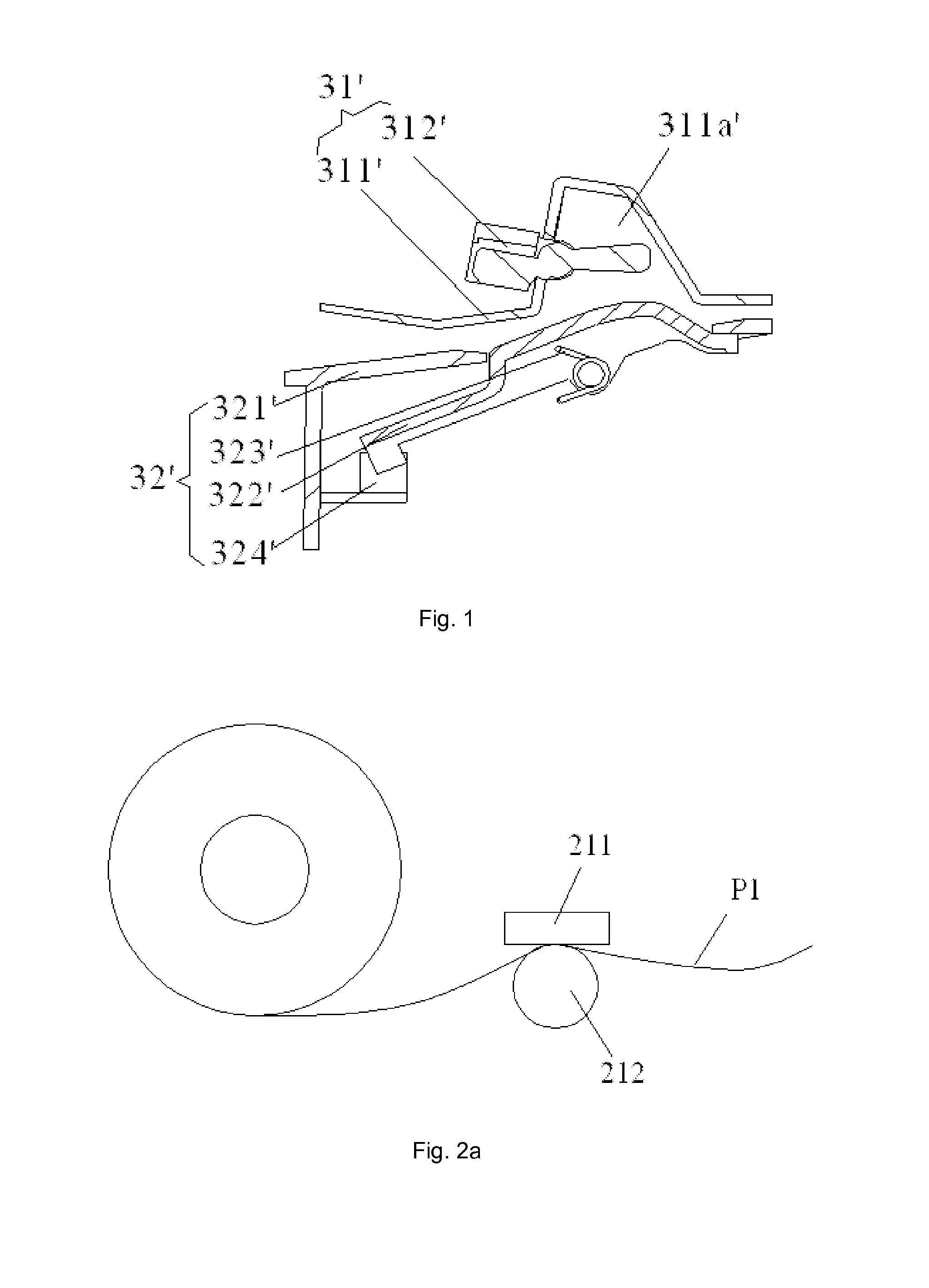
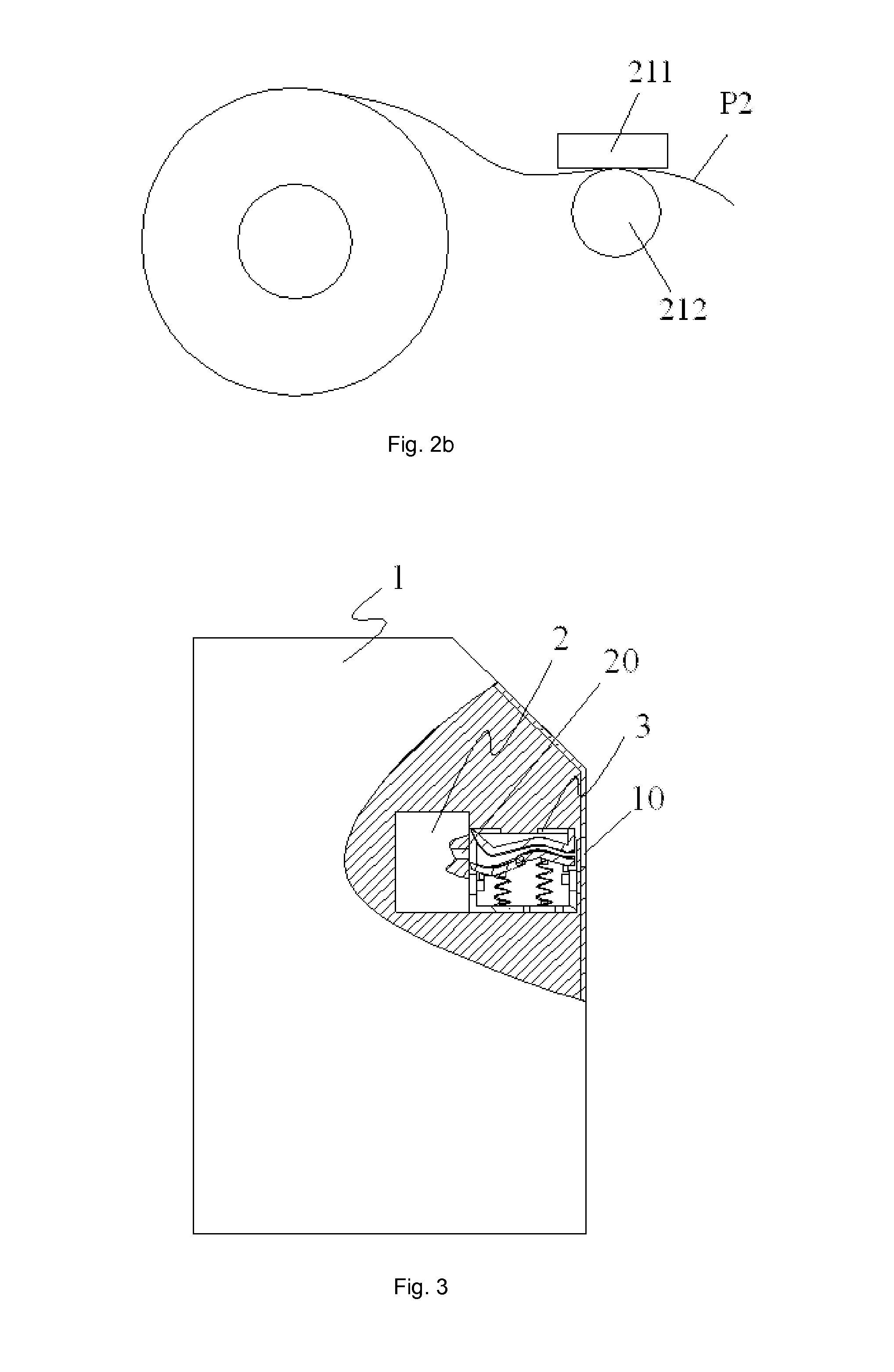
[0070]FIG. 3 is a schematic diagram illustrating the first embodiment of a terminal equipment according to the present invention. As shown in FIG. 3, the terminal equipment comprises a terminal main body 1, a printing device 2 and a paper discharge mechanism 3. The printing device 2 is set in the terminal main body 1 and the printing device 2 is provided with a first paper exit 20 configured to output printed paper from the printing device; the terminal main body 1 is provided with a second paper exit 10 configured to discharge paper out of the terminal main body 1; the paper discharge mechanism 3 is located between the first paper exit 20 and the second paper exit 10 and configured to connect the first paper exit 20 and the second paper exit ...


PUM

PropertyMeasurementUnit
Widthaaaaaaaaaa
Distanceaaaaaaaaaa

Abstract

The paper discharge mechanism comprises: a first side passage plate and a second side passage plate between which an S-shaped paper conveying passage is formed, wherein the second side passage plate comprises a paper jam detection plate and a paper pullout detection plate both pivotally connected on a frame; a first elastic element biasing the paper jam detection plate and a second elastic element biasing the paper pullout detection plate; and a first sensor and a second sensor. A surface of the paper jam detection plate facing paper is concave and is held against the paper and rotates in the direction away from the first side passage plate during paper jam; a surface of the paper pullout detection plate facing the paper is convex and is held against the paper and rotates in the direction away from the first side passage plate during paper pullout.

Description

[0001]The present application claims the priority of a Chinese invention patent application, Application Number 201110237973.3, entitled “Paper discharge mechanism, printing device and terminal equipment”, filed with the State Intellectual Property Office of the P.R.C on Aug. 18, 2011, the entire disclosure of which is incorporated herein by reference.TECHNICAL FIELD OF THE INVENTION[0002]The present invention relates to the field of printer, and in particular to a paper discharge mechanism, and a printing device and a terminal equipment having the paper discharge mechanism.BACKGROUND OF THE INVENTION[0003]Self-service terminal equipments have been widely applied in various fields, and self-service terminals are generally provided with printing devices, e.g. an Automated Teller Machine (ATM) is capable of printing a transaction voucher, and a self-service telephone bill enquiry machine is capable of printing a telephone bill etc.[0004]Currently, such self-service terminal equipments...

Claims


Application Information

Patent Timeline
IPC IPC(8): B41J29/393B65H26/02
CPCB65H26/02B41J29/393B65H2301/3123B65H2404/6111B65H2407/10B65H2511/20B65H2553/00B41J11/006B41J15/046B65H2402/443B65H2511/528B65H2801/12B65H29/52B65H2301/51212B65H2408/13G07B5/08B65H2220/09B65H2220/02B65H2220/11B65H2220/01B65H2220/03G07B5/00
Inventor ZHANG, ZHENGMINTANG, XIAOJIEJIANG, TIANXINYANG, MIN
Owner SHANDONG NEW BEIYANG INFORMATION TECH CO LTD
Why Eureka
Try Eureka