Comb MEMS Device and Method of Making a Comb MEMS Device

a comb and microphone technology, applied in the field of comb mems devices and a method for making comb mems devices, can solve the problems of small mems microphones and small ones

Inactive Publication Date: 2014-07-17
INFINEON TECH AG
View PDF14 Cites 37 Cited by
  • Summary
  • Abstract
  • Description
  • Claims
  • Application Information

AI Technical Summary

Problems solved by technology

In particular, MEMS microphones may become smaller and smaller because electroni...

Method used


Image

  • Comb MEMS Device and Method of Making a Comb MEMS Device
  • Comb MEMS Device and Method of Making a Comb MEMS Device
  • Comb MEMS Device and Method of Making a Comb MEMS Device

Examples


Embodiment Construction

[0014]The making and using of the presently preferred embodiments are discussed in detail below. It should be appreciated, however, that the present invention provides many applicable inventive concepts that can be embodied in a wide variety of specific contexts. The specific embodiments discussed are merely illustrative of specific ways to make and use the invention, and do not limit the scope of the invention.

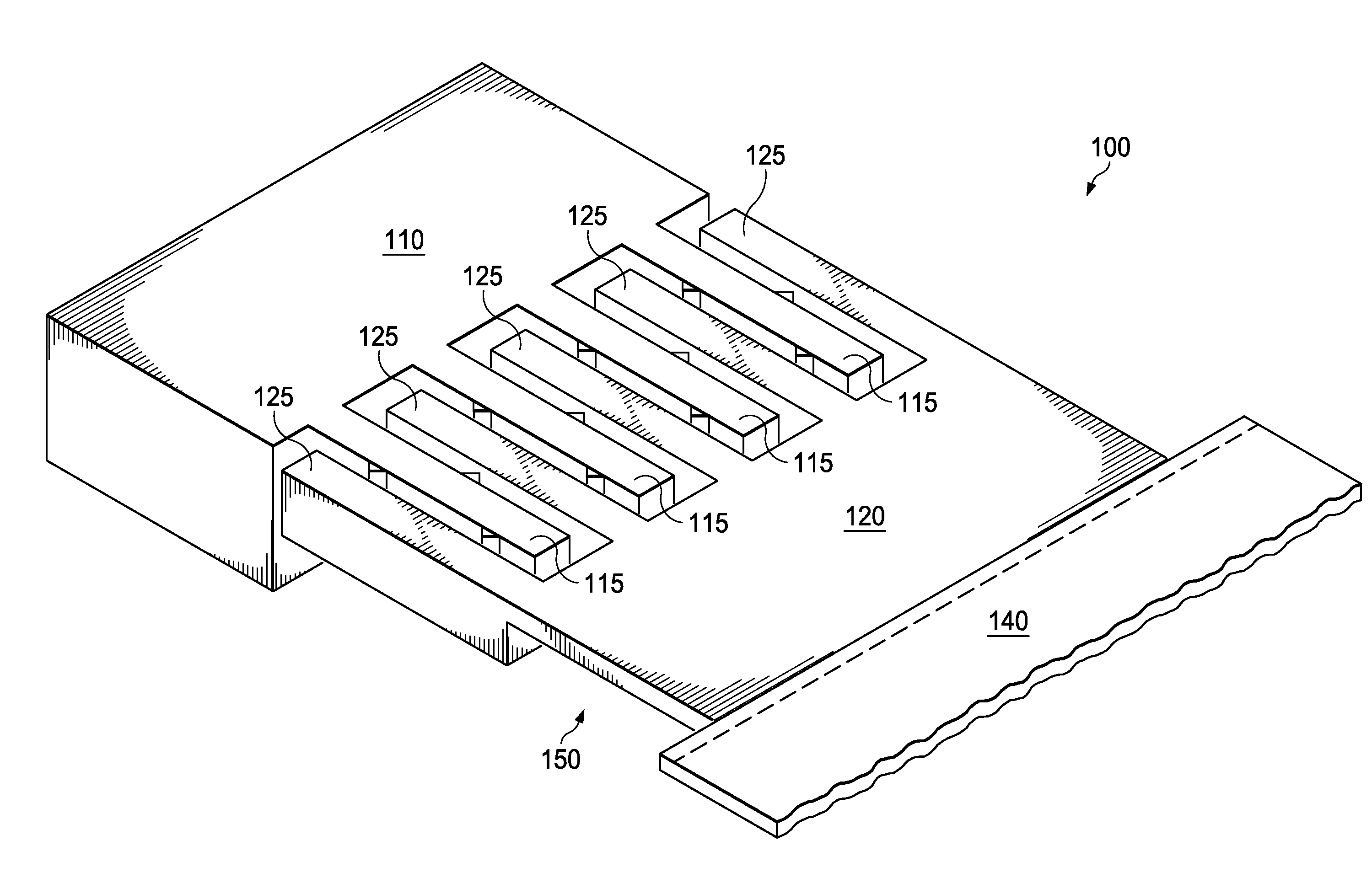
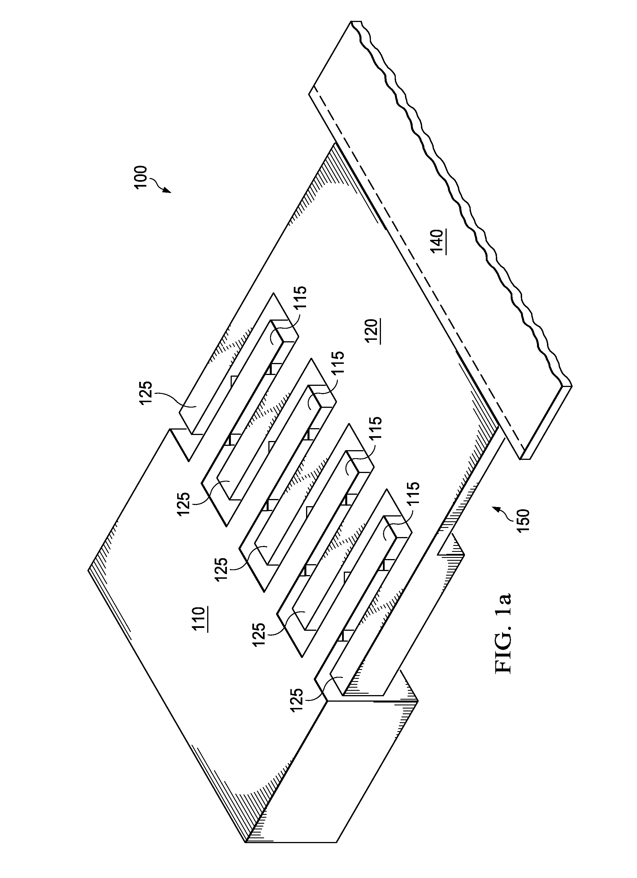
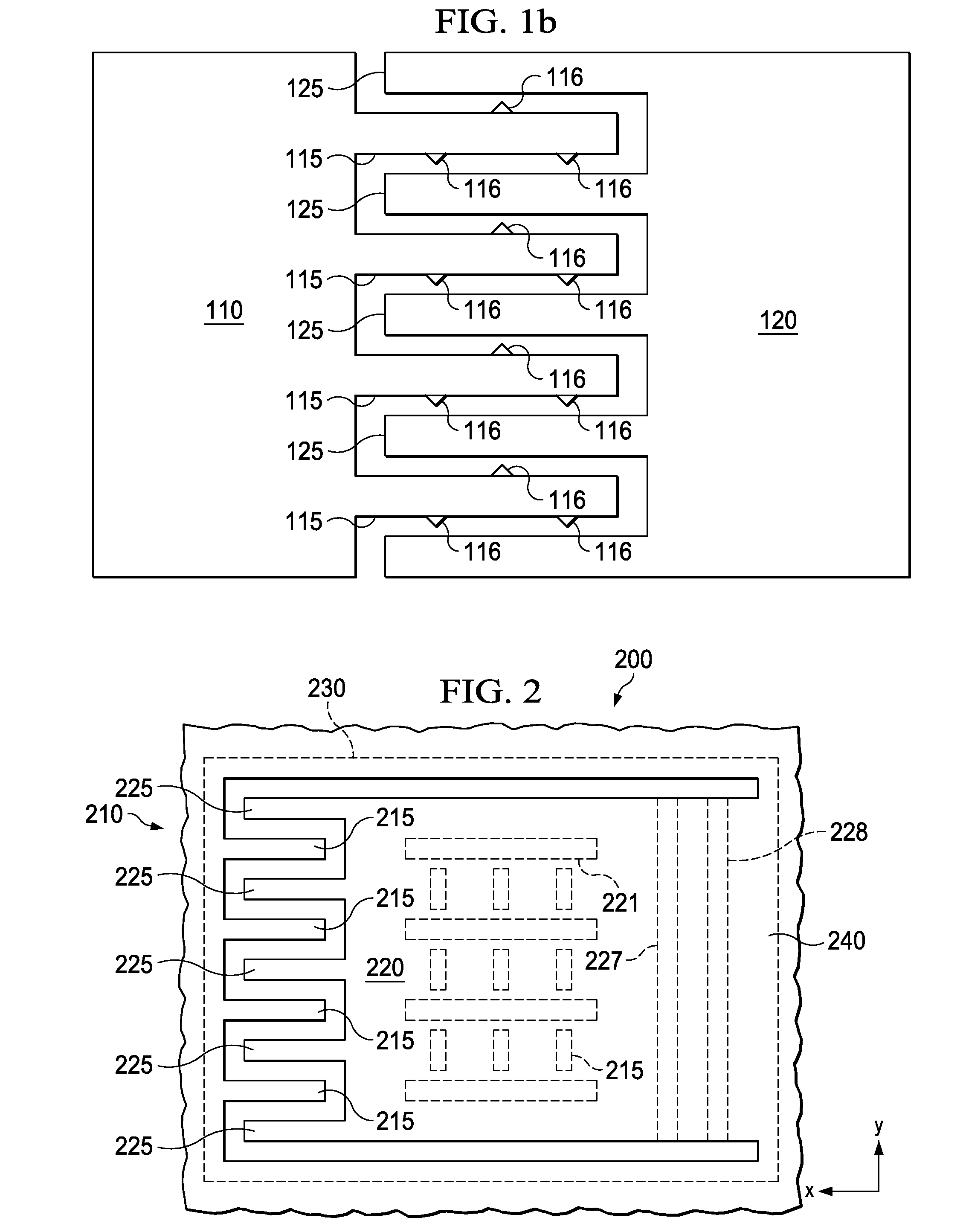
[0015]The present invention will be described with respect to preferred embodiments in a specific context, namely a silicon comb microphone. The invention may also be applied, however, to other microphones and MEMS devices.

[0016]Standard condenser microphones comprise a parallel plate capacitance. A change in distance (gap) between a membrane (the first plate) and a backplate (second plate) measures an incoming sound signal. Based on this construction air moves through the perforations in the backplate an unavoidable generates noise and, therefore, limits signal to noise rati...


PUM

PropertyMeasurementUnit
Dielectric polarization enthalpyaaaaaaaaaa
Electrical conductoraaaaaaaaaa
Metallic bondaaaaaaaaaa

Abstract

A MEMS device and a method to manufacture a MEMS device are disclosed. An embodiment includes forming trenches in a first main surface of a substrate, forming conductive fingers by forming a conductive material in the trenches and forming an opening from a second main surface of the substrate thereby exposing the conductive fingers, the second main surface opposite the first main surface.

Description

TECHNICAL FIELD[0001]The present invention relates generally to a comb MEMS device and a method for making a comb MEMS device. In particular embodiments, the invention relates to a silicon comb microphone.BACKGROUND[0002]Over the past years a desire for smaller electronic form factors, smaller power consumption and increased performance has driven an integration of MEMS devices. In particular, MEMS microphones may become smaller and smaller because electronic devices such as, e.g., cell phones, laptops, and tablets become smaller and smaller.SUMMARY OF THE INVENTION[0003]In accordance with an embodiment of the present invention, a method for making a MEMS device comprises forming trenches in a first main surface of a substrate, forming conductive fingers by forming a conductive material in the trenches and forming an opening from a second main surface of the substrate thereby exposing the conductive fingers, the second main surface being opposite the first main surface.[0004]In acco...

Claims


Application Information

Patent Timeline
IPC IPC(8): B81B3/00B81C1/00
CPCB81C1/0015B81B3/0005B81B3/001B81B2203/0136H04R19/02B81B2201/0257B81C1/00968B81C2201/112
Inventor DEHE, ALFONS
Owner INFINEON TECH AG
Why Eureka
Try Eureka