Compliant Pin With Improved Insertion Capabilities

a technology of compliant pins and mounting pins, applied in the direction of electrical equipment, printed circuits, coupling device connections, etc., can solve the problems of pin bends or buckles, pins may be lacking structural integrity, and the cross-section of some pins may be lacking in structural integrity, so as to achieve better resistance to buckling

Active Publication Date: 2014-07-17
MOLEX INC
View PDF17 Cites 13 Cited by
  • Summary
  • Abstract
  • Description
  • Claims
  • Application Information

AI Technical Summary

Benefits of technology

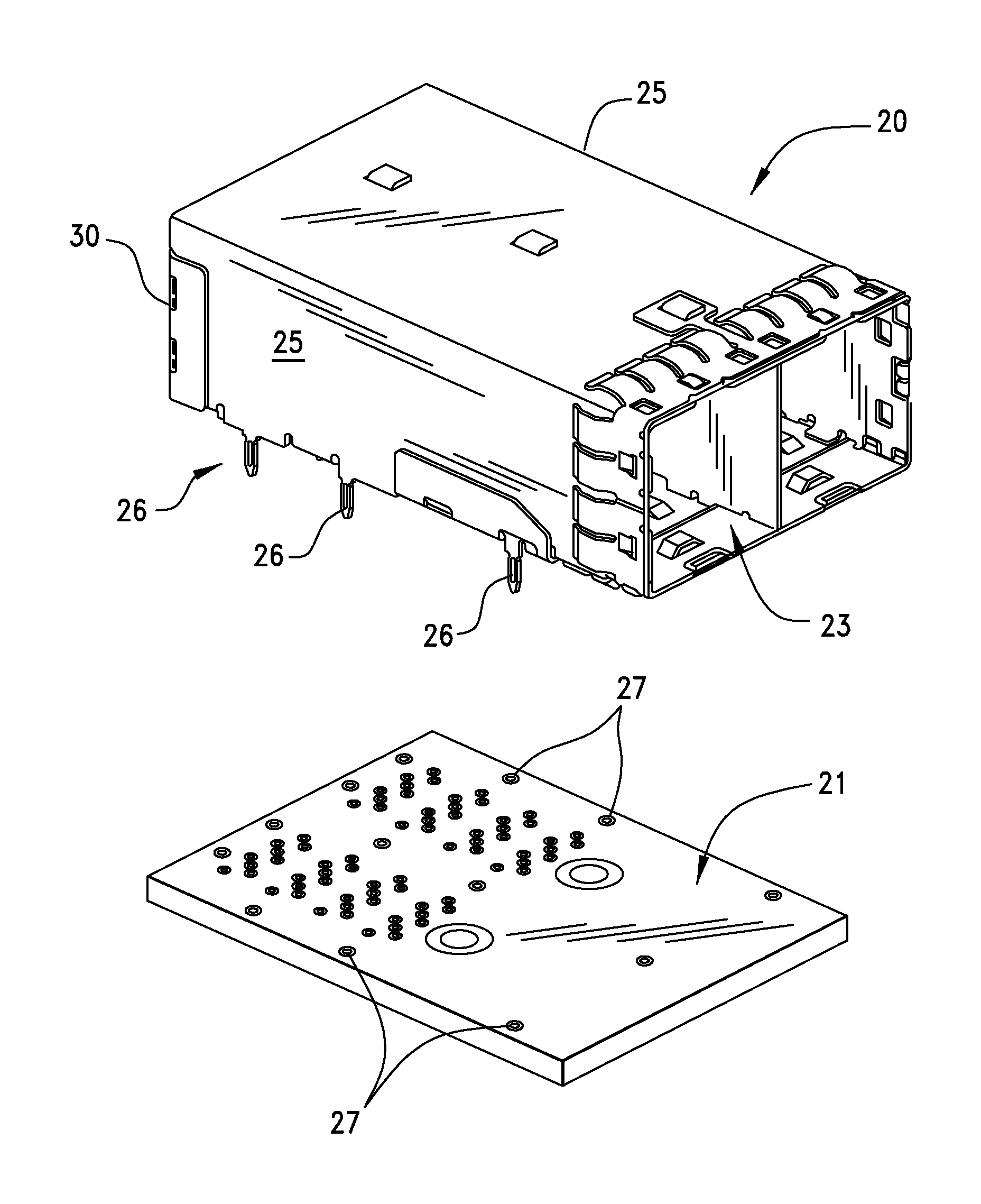
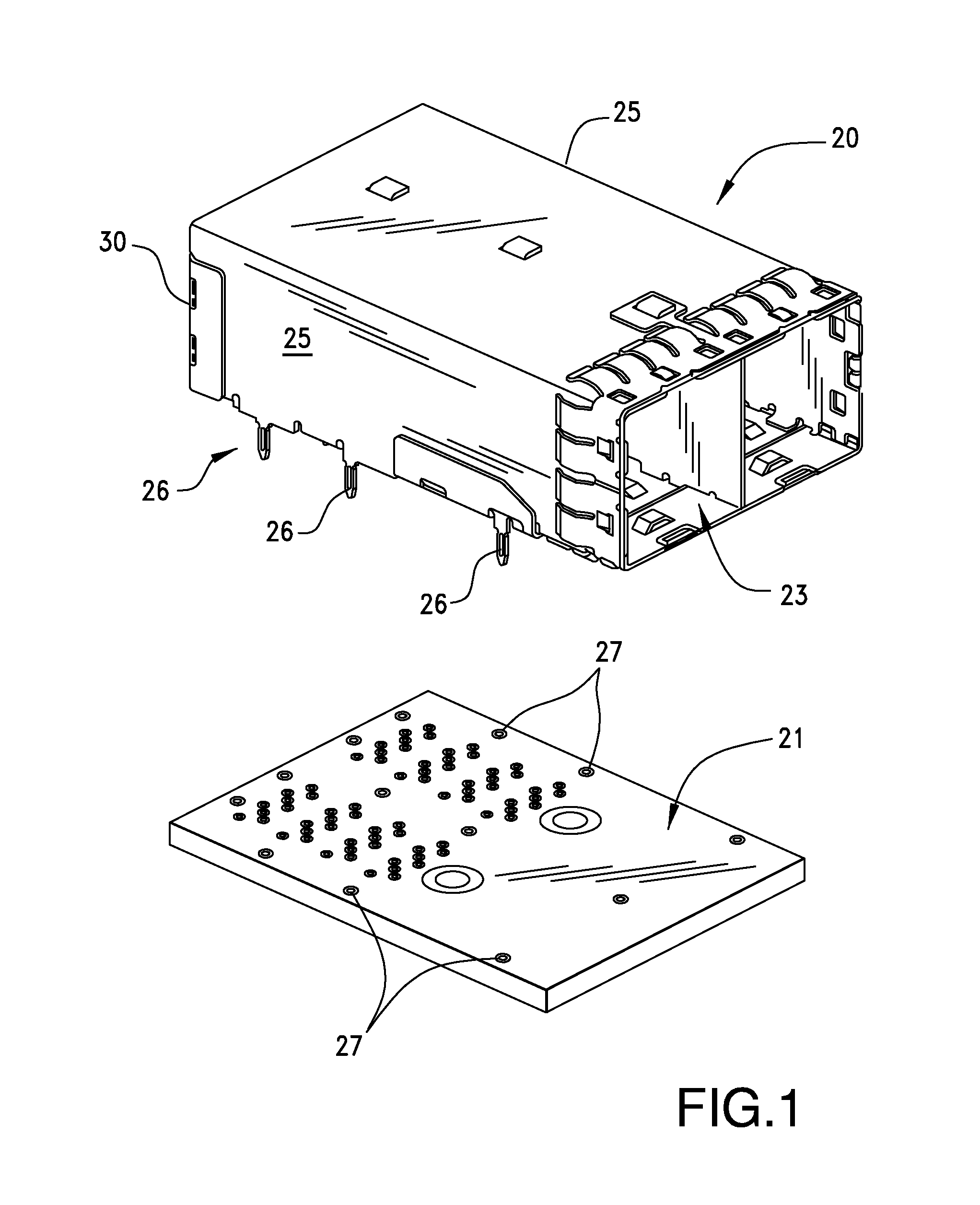
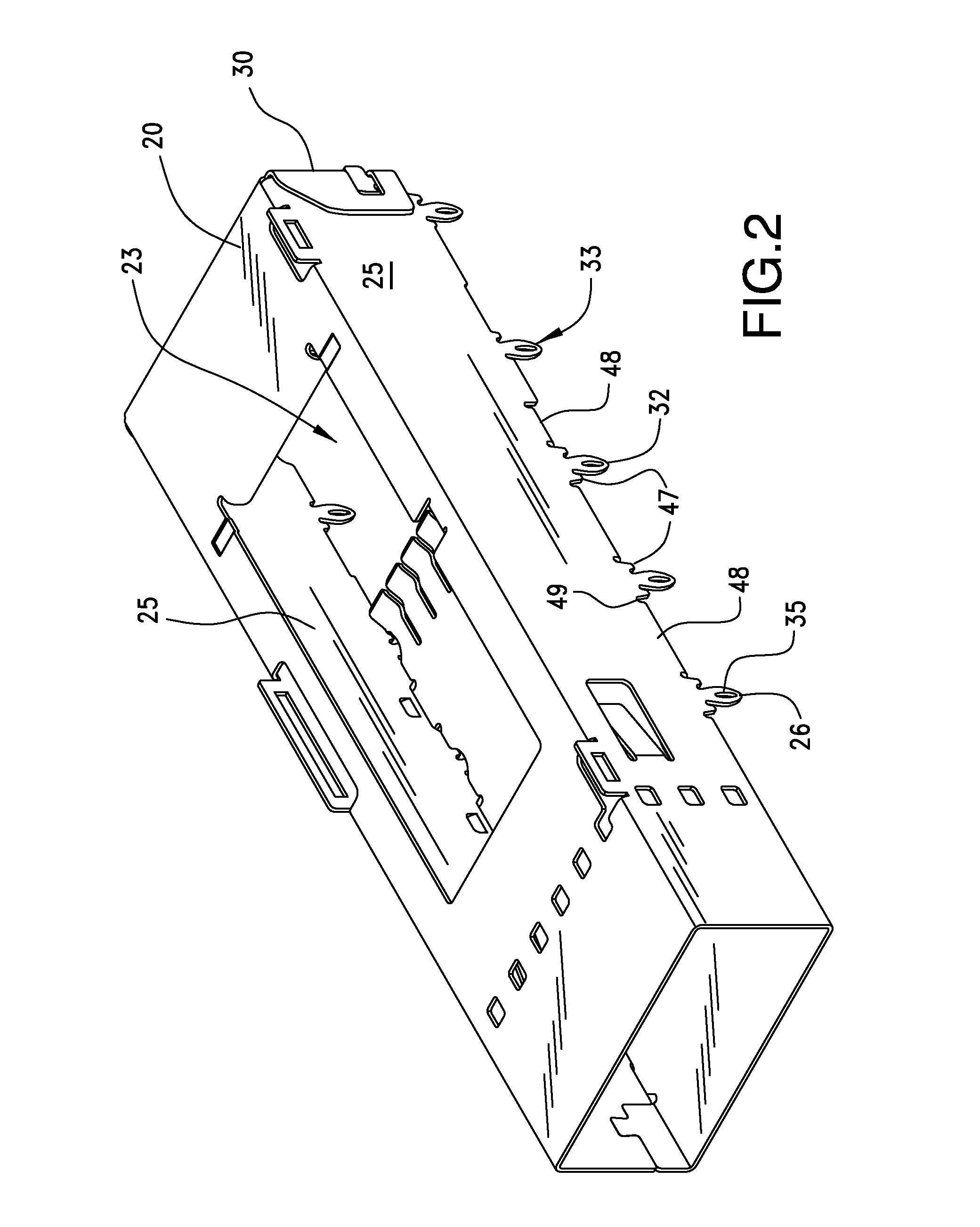
[0006]Accordingly, there is provided an improved compliant pin that has a cross-section configured to better resist buckling during insertion into a circuit board opening.

Problems solved by technology

There are problems in the use of press-fit compliant pins and these problems include inadequate performance during insertion into and retention by a circuit board.
The cross-section of some pins may be lacking in structural integrity such that those pins may bend or buckle when the pins are inserted into their associated through holes.
If the pins buckle during insertion they will not be fully inserted into the holes and may deform more than expected.
This lack of full insertion and / or excessive deformation negatively affects the electrical contact between the pins and the surrounding vias and requires the cage to be removed and replaced, but in doing so, the buckled configuration of the pins may give rise to the possibility of damage to the expensive circuit board.
Similarly, if the pins buckle during insertion, they may provide adequate electrical contact with the circuit board but their retention capability may be diminished to the point where the electrical contact becomes sporadic and intermittent after the device in which the cage is used proceeds through assembly, packing, shipping and installation at an end user.
This intermittent contact may not be discovered until the product is placed into service at the end user or shortly thereafter, thereby necessitating return of the device to the manufacturer.

Method used


Image

  • Compliant Pin With Improved Insertion Capabilities
  • Compliant Pin With Improved Insertion Capabilities
  • Compliant Pin With Improved Insertion Capabilities

Examples


Embodiment Construction

[0022]While the Present Disclosure may be susceptible to embodiment in different forms, there is shown in the Figures, and will be described herein in detail, specific embodiments, with the understanding that the Present Disclosure is to be considered an exemplification of the principles of the Present Disclosure, and is not intended to limit the Present Disclosure to that as illustrated.

[0023]As such, references to a feature or aspect are intended to describe a feature or aspect of an example of the Present Disclosure, not to imply that every embodiment thereof must have the described feature or aspect. Furthermore, it should be noted that the description illustrates a number of features. While certain features have been combined together to illustrate potential system designs, those features may also be used in other combinations not expressly disclosed. Thus, the depicted combinations are not intended to be limiting, unless otherwise noted.

[0024]In the embodiments illustrated in ...


PUM


Abstract

A compliant pin for use with a shielding cage or electrical connector is disclosed that has improved insertion capabilities that increase the resistance of the compliant pin to buckling during mounting of the cage or connector to a circuit board. The pin has a base and tip portion that are interconnected together by a body portion. An opening is disposed in the pin body portion and the top edge of the opening is positioned at a level therein that is spaced apart from and beneath the top surface of the circuit board. In another embodiment, the pin opening is generally non-symmetrical with a configuration that approximates a triangle, i.e., the wider base portion of the pin opening is closer to the pin tip portion than the narrower, apex portion of the pin opening.

Description

BACKGROUND OF THE PRESENT DISCLOSURE[0001]The Present Disclosure relates generally to board mounted connectors, and more particularly, to such connectors having improved compliant mounting pins that offer beneficial insertion and retention capabilities.[0002]Many electronic devices utilize internal circuit boards for circuitry and as a platform upon which to mount integrated circuits, switches, components and the like, including connectors. These connectors are often surrounded with a conductive shielding member that takes the form of a cage to provide grounding and shielding against electromagnetic interference radiation, known as “EMI.” These shields may be mounted to the surface of the circuit board, such as by soldering, or they may be provided with a plurality of members in the form of mounting pins that extend downwardly therefrom and which are received in openings formed in the circuit board. These openings are formed as plated through holes, or “vias,” directly in the circui...

Claims


Application Information

Patent Timeline
Patent Type & Authority Applications(United States)
IPC IPC(8): H01R12/71
CPCH01R12/71H01R12/585H01R13/6594
Inventor HIRSCHY, CHRISTOPHER D.
Owner MOLEX INC
Why Eureka
Try Eureka