
Barbell assembly having impact absorbing weights and swivel end

Active Publication Date: 2014-07-17
SIDES JR RICHARD D
View PDF18 Cites 37 Cited by
  • Summary
  • Abstract
  • Description
  • Claims
  • Application Information

AI Technical Summary

Benefits of technology

This patent describes a barbell assembly made with impact-absorbing weights that can be used on any exercise or competition surface without damaging it. The weights can be inflated and affixed to a vehicle wheel or tire. The assembly also includes a swivel hook that allows for weight pushing and pulling with a tether attached to the swivel hook. The technical effect of this invention is to provide a safer, more effective, and reduced noise training tool for individuals who work out at gyms or at home.

Problems solved by technology

Depending on the type of surface, it is also possible that the bar and / or the free weights can be damaged from the impact with the exercise or competition surface.
However, the mat only protects the area of the surface covered by the mat.
Furthermore, the mat does not protect the user from being struck by the heavy free weights, and therefore, does not increase the safety of the user.
Oftentimes, the plug is dislodged during use and the fill opening is compromised.
As a result, the fill material leaks from the opening making the barbell or dumbbell unusable.
However, the resilient raised projections of the Januszek exercise device weight and the band of the weight taught by the Dorn patent do not adequately protect the exercise or competition surface from damage in the event that the barbell or dumbbell is dropped.
However, a barbell assembly having conventional weights made of a metal or plastic material, whether or not coated or covered with a circumferential band of rubber, foamed plastic or other somewhat elastic material, is not suited for performing weight pushing and / or weight pulling exercises.
In particular, as the amount of weight on the barbell is increased, conventional weights tend to gouge, scratch, dig into, or otherwise damage the surface on which the barbell assembly is pushed or pulled.

Method used


Image

  • Barbell assembly having impact absorbing weights and swivel end
  • Barbell assembly having impact absorbing weights and swivel end
  • Barbell assembly having impact absorbing weights and swivel end

Examples


Embodiment Construction

[0032]The invention will be described more fully hereinafter with reference to the accompanying drawings in which one or more exemplary embodiments are shown. However, it is to be understood that the invention may be embodied in many different forms and should not be construed as limited to the exemplary embodiments set forth herein. Exemplary embodiments of the invention are provided herein so that this disclosure will fully and completely convey the broad scope of the invention and to enable one of ordinary skill in the art to make, use and practice the invention without undue experimentation. As previously mentioned, like reference characters in the detailed description and the accompanying drawing figures refer to the same or similar parts, elements, components or assemblies of the invention.

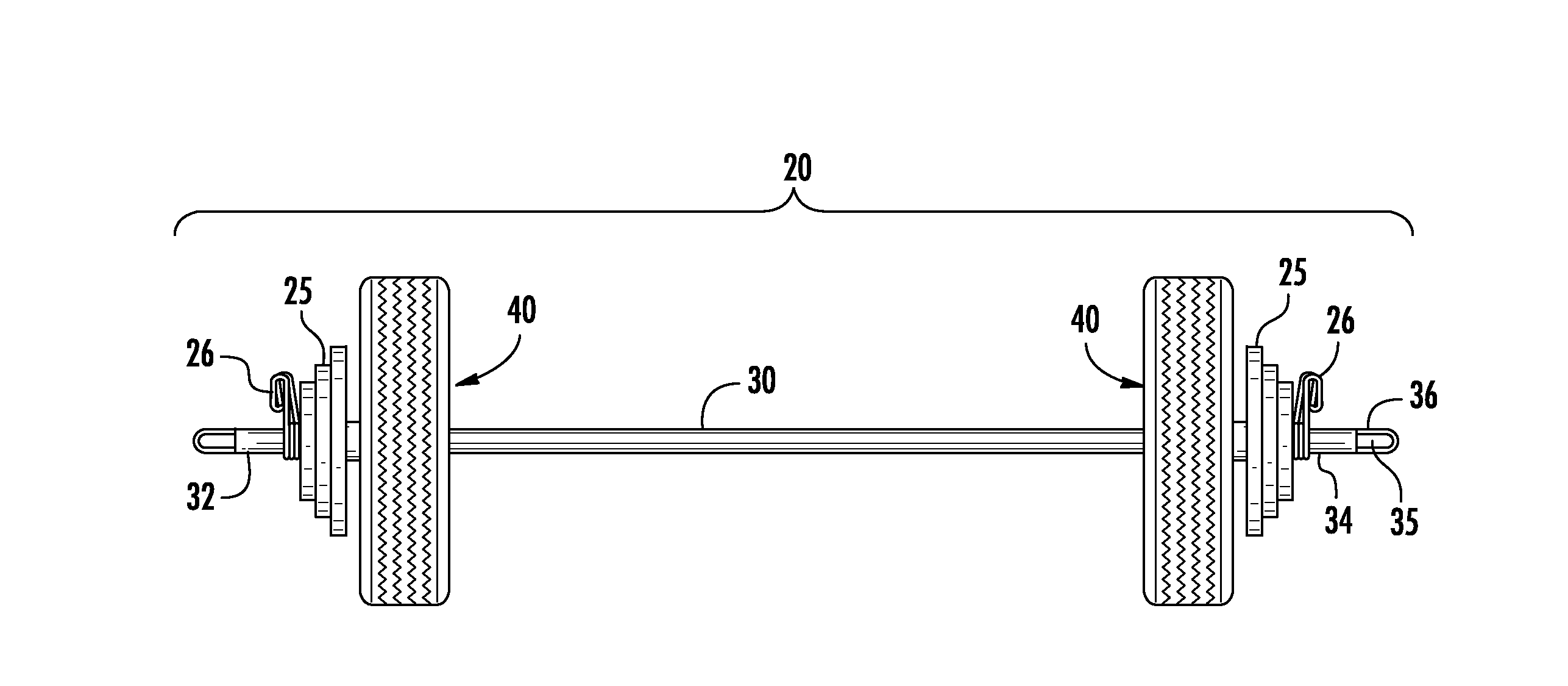
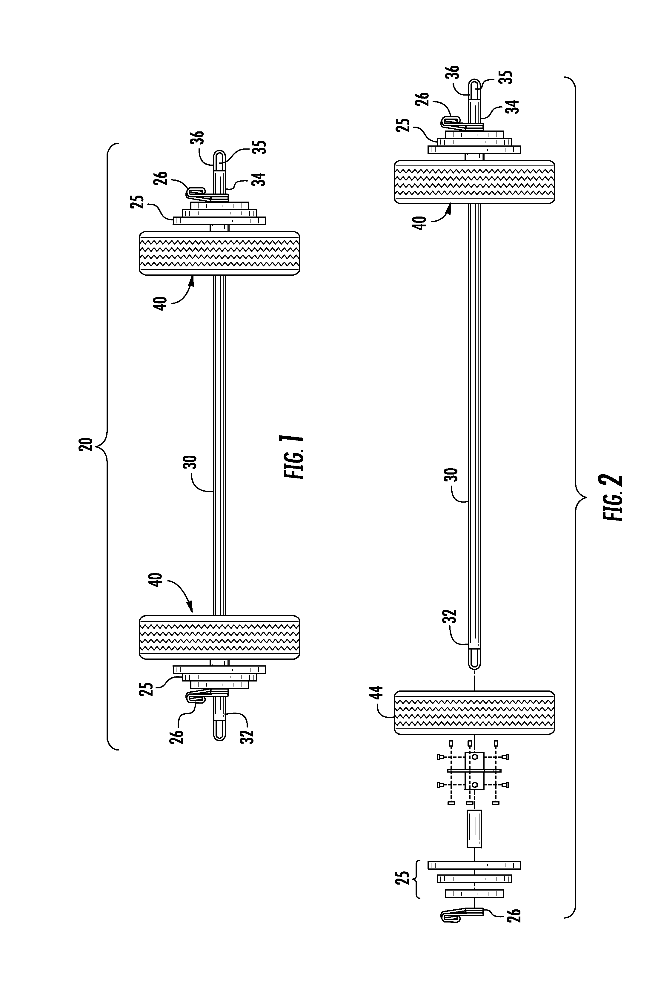
[0033]An exemplary embodiment of a barbell assembly constructed according to the invention is shown in FIG. 1 and FIG. 2. As shown, the barbell assembly, indicated generally by reference cha...


PUM


Abstract

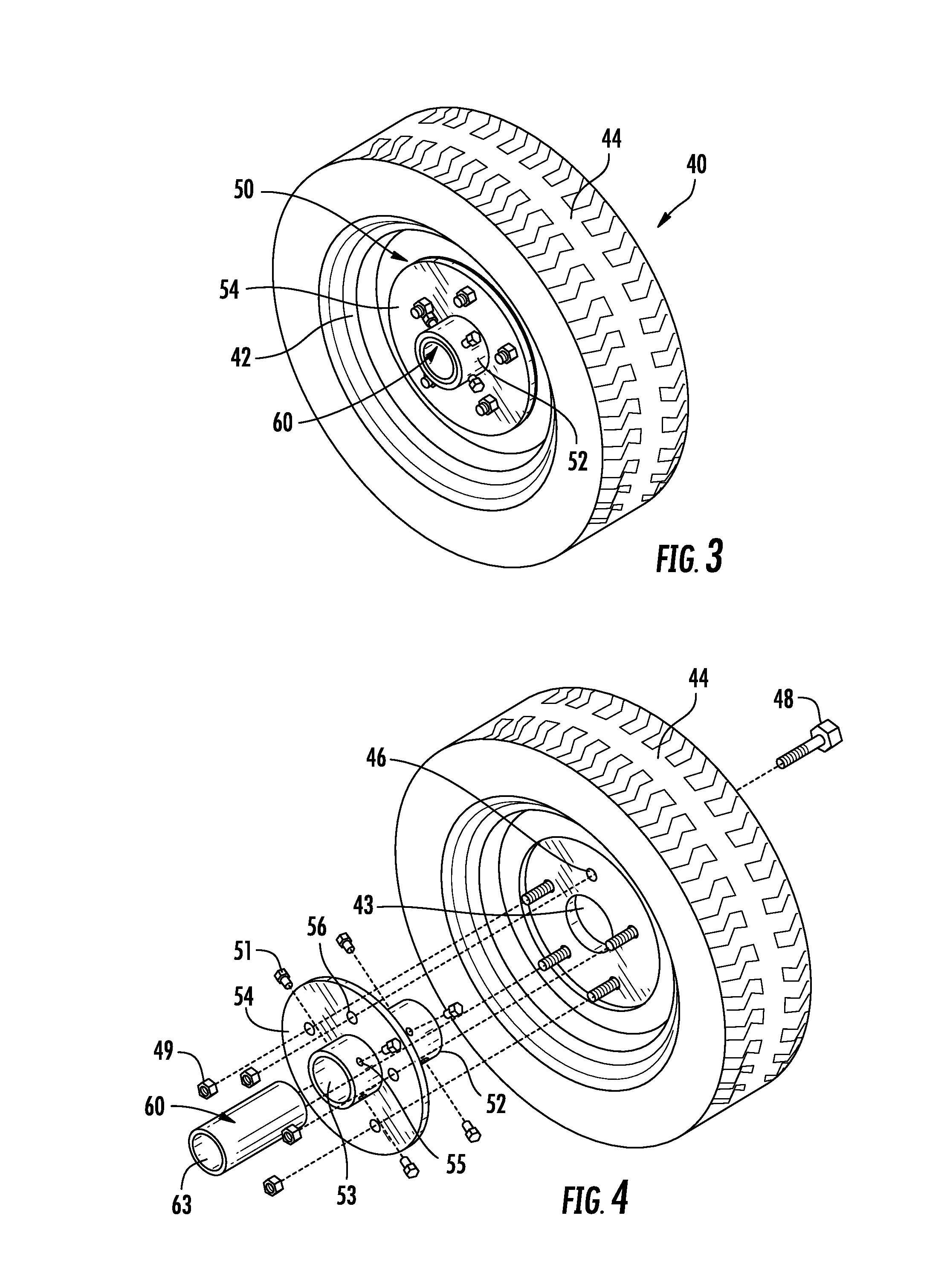
A barbell assembly includes a bar and a weight subassembly adjacent each end of the bar. Each weight subassembly includes a wheel with a predetermined pattern of through holes and an inflatable component around the periphery of the wheel. A hub defines a flange having a plurality of through holes corresponding to the through holes on the wheel for securing the wheel to the hub with fasteners. The hub is secured to the bar with fasteners, or the flange is secured to the bar by welding or with fasteners. An outer end of the bar is provided with a U-shaped swivel having a hook that rotates freely relative to the outer end and the grip portion of the bar. The barbell assembly may be utilized to perform weight training exercises without causing damage to an exercise surface, and may be locked to an immovable fixture using a tether and a lock.

Description

CROSS-REFERENCE To RELATED APPLICATION[0001]This application is a continuation-in-part of U.S. application Ser. No. 14 / 071,632, filed on Nov. 4, 2013, which in turn is a continuation-in-part of U.S. application Ser. No. 13 / 707,749, filed on Dec. 7, 2012, the entire disclosures of which are incorporated herein by reference.FIELD OF THE INVENTION[0002]The invention relates generally to a barbell assembly, and more particularly, to a barbell assembly having impact absorbing weights mounted on a bar and a swivel adjacent at least one end of the bar. A barbell assembly constructed in accordance with the present invention can be used on any exercise or competition surface in any location without damaging the surface in the event the barbell assembly is dropped, while reducing noise and providing increased safety to the user. In addition, a barbell assembly constructed in accordance with the present invention can be used to perform weight training exercises that cannot be performed with a ...

Claims


Application Information

Patent Timeline
IPC IPC(8): A63B21/072
CPCA63B21/0724A63B21/0618A63B23/047A63B2225/72A63B21/4005
Inventor SIDES, JR., RICHARD D.
Owner SIDES JR RICHARD D
Learn More