Cartridge, developing cartridge, process cartridge and image forming apparatus

a technology of developing cartridges and image forming apparatuses, which is applied in the direction of electrographic process apparatus, instruments, optics, etc., can solve the problems of difficult to discharge toner in some cases, and achieve the effect of reducing the remaining amount of developer

Active Publication Date: 2014-07-31
CANON KK
View PDF14 Cites 23 Cited by
  • Summary
  • Abstract
  • Description
  • Claims
  • Application Information

AI Technical Summary

Benefits of technology

[0008]The present invention has solved the above problem. A principal object of the present invention is to provide a cartridge capable of permitting satisfactory discharge of a developer contained in a flexible developer bag to decrease a remaining amount of the developer.

Problems solved by technology

However, in JP-A Hei 4-66980, in a constitution in which a bottom surface of the toner bag is not provided with inclination (tilt) enough to permit fall (drop) of the toner by its own weight, it is difficult to discharge the toner in some cases.

Method used


Image

  • Cartridge, developing cartridge, process cartridge and image forming apparatus
  • Cartridge, developing cartridge, process cartridge and image forming apparatus
  • Cartridge, developing cartridge, process cartridge and image forming apparatus

Examples


embodiment 1

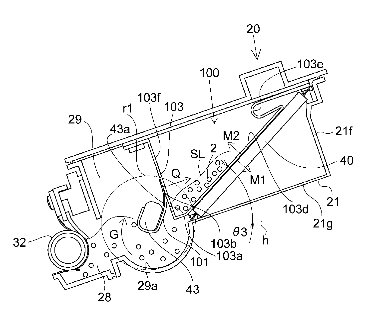
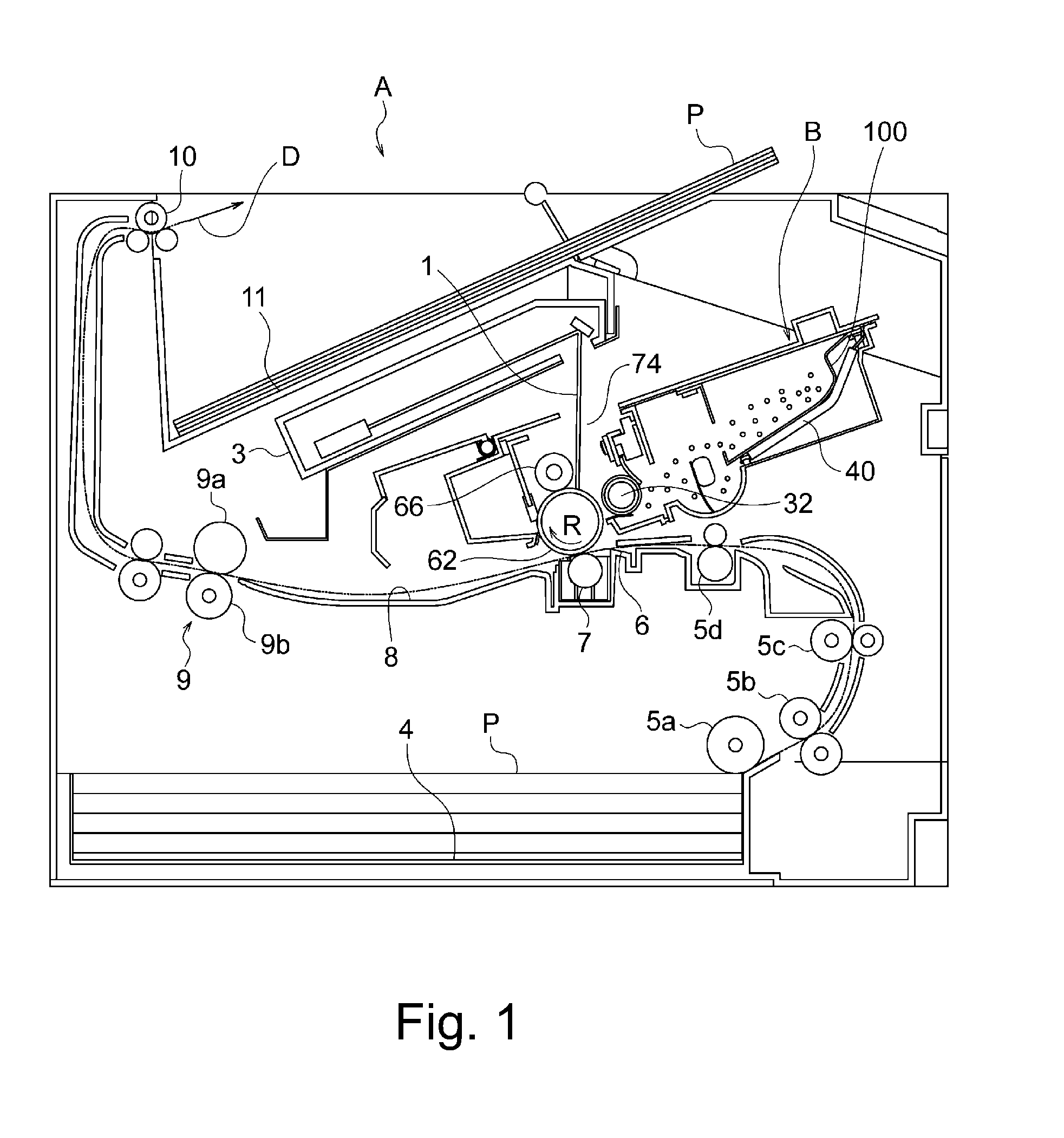
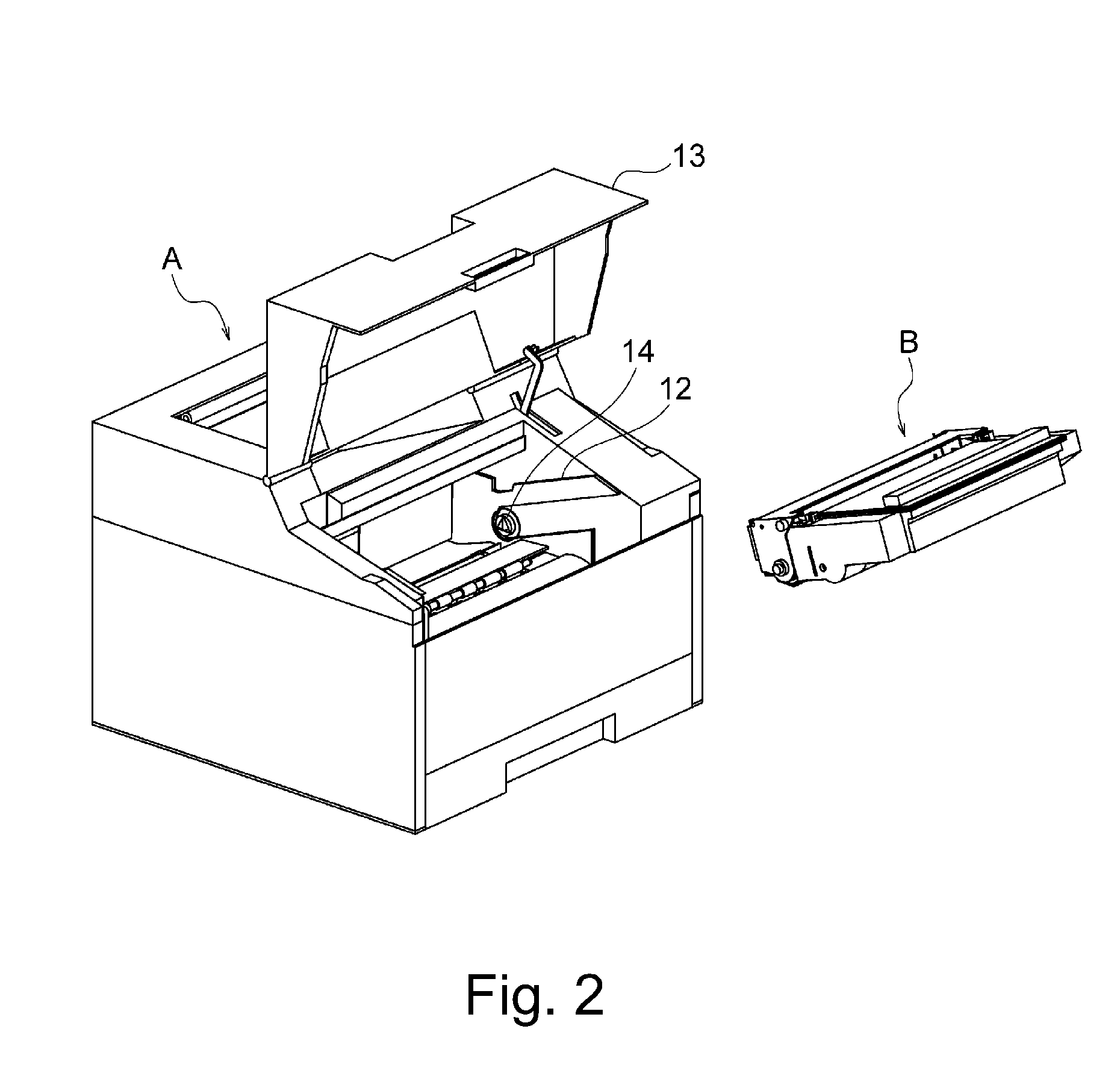
[0036]First, structures of the cartridge, the developing cartridge, the process cartridge and the image forming apparatus according to the present invention in this embodiment will be described with reference to FIGS. 1 to 13. Incidentally, in the following description, a rotational axis direction of a photosensitive drum 62 as an image bearing member on which an electrostatic latent image is to be formed on a surface of the photosensitive drum 62 is referred to as a longitudinal direction of a cartridge B.

[0037]Further, with respect to the longitudinal direction of the cartridge B, a side where the photosensitive drum 62 receives a driving force from a main assembly of an image forming apparatus A (image forming apparatus main assembly) is referred to as a driving side (where a driving force-receiving portion 63a shown in a right side of FIG. 5 is provided), and its opposite side is referred to as a non-driving side.

[0038]A general structure of the image forming apparatus A and an ...

embodiment 2

[0151]Structure of a cartridge, a developing cartridge, a process cartridge and an image forming apparatus according to the present invention in Embodiment 2 will be described with reference to FIGS. 14 to 17. Incidentally, constituent elements which are the same as those in Embodiment 1 are represented by the same reference numerals or symbols and will be omitted from description.

[0152]In Embodiment 1, the feeding member 43 as the acting member is constituted in the elongated circular shape in cross section, and the feeding member 43 itself is spaced from the front surface 103f of the toner accommodating bag 103 of the toner bag 100. Further, the constitution in which the seal member 101 and the sheet member 43a which are fixed to the feeding member 43 at one end portion periodically contact the connecting portion 103b at the front surface 103f of the toner accommodating bag 103 with the rotation of the feeding member 43 was employed.

[0153]In this embodiment, as shown in FIG. 14, a...

embodiment 3

[0187]Structure of a cartridge, a developing cartridge, a process cartridge and an image forming apparatus according to the present invention in Embodiment 3 will be described with reference to FIGS. 18 to 21. Incidentally, constituent elements which are the same as those in Embodiments 1 and 2 are represented by the same reference numerals or symbols and will be omitted from description.

[0188]In this embodiment, tension coil springs 201 and 202 as the elastic member are provided inside the toner accommodating bag 103 as the frame in substantially parallel with each other with respect to the longitudinal direction (left-right direction in FIG. 20) of the cartridge B at different positions in height. As a result, the tension coil springs 201 and 202 positively act on the toner 2 in the toner bag 100 to improve the toner discharging property.

[0189]FIG. 18 is an exploded perspective view for illustrating fixing positions of the tension coil springs 201 and 202 in the toner accommodatin...


PUM


Abstract

A cartridge detachably mountable to a main assembly of an image forming apparatus includes: a frame; a flexible developer bag, provided with an opening and provided inside the frame, for containing a developer; and an elastic member for discharging the developer through the opening by acting on the developer bag. The elastic member is extended from a free state by contact with the developer bag, and elastic energy accumulated by extension of the elastic member acts on the developer bag to discharge the developer through the opening.

Description

FIELD OF THE INVENTION AND RELATED ART[0001]The present invention relates to a cartridge, a developing cartridge, a process cartridge and an image forming apparatus using the developing cartridge.[0002]A device, including a developing roller, for visualizing an electrostatic latent image, with a developer by using the developing roller, formed on a surface of an electrophotographic photosensitive drum as an image bearing member is a developing device. Here, the developing cartridge is prepared by integrally assembling the developing device into a cartridge, and is to be detachably mounted to a main assembly of an electrophotographic image forming apparatus.[0003]Further, the process cartridge is prepared by integrally assembling the electrophotographic photosensitive drum and the developing device actable on the electrophotographic photosensitive drum into a cartridge, and is to be detachably mounted to the electrophotographic image forming apparatus main assembly. Further, the elec...

Claims


Application Information

Patent Timeline
Patent Type & Authority Applications(United States)
IPC IPC(8): G03G15/08
CPCG03G15/0874G03G2215/068G03G2215/0682
Inventor NAKAMURA, YUUKIBATORI, YOSHIYUKIHAMADA, TAKATOSHITAKEUCHI, TOSHIAKIMAKIGUCHI, DAISUKEKAWAMURA, TOMOFUMI
Owner CANON KK
Why Eureka
Try Eureka