Dispensing heads with fluid puddle limiting surface features

Active Publication Date: 2014-08-07
HEWLETT PACKARD DEV CO LP
View PDF6 Cites 3 Cited by
  • Summary
  • Abstract
  • Description
  • Claims
  • Application Information

AI Technical Summary

Problems solved by technology

Incomplete dispensing into wellplates or streaks, spots or other undesirable artifacts on a printed media can result if such puddles achieve sufficient volume.

Method used


Image

  • Dispensing heads with fluid puddle limiting surface features
  • Dispensing heads with fluid puddle limiting surface features
  • Dispensing heads with fluid puddle limiting surface features

Examples


Embodiment Construction

Introduction

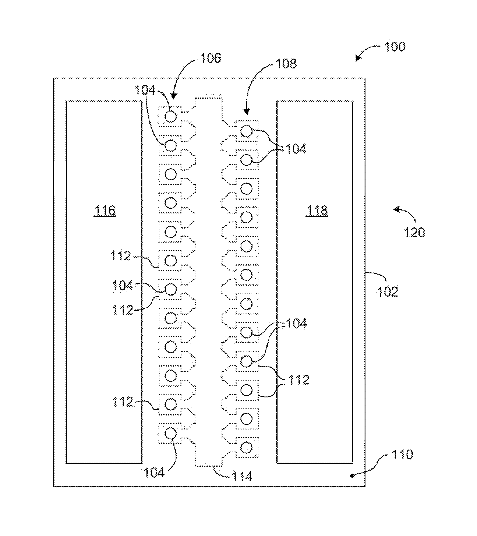
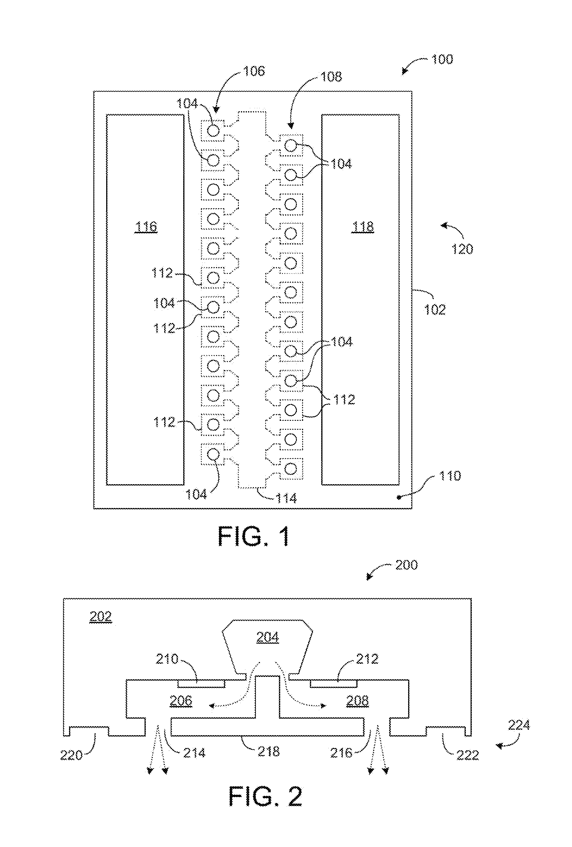
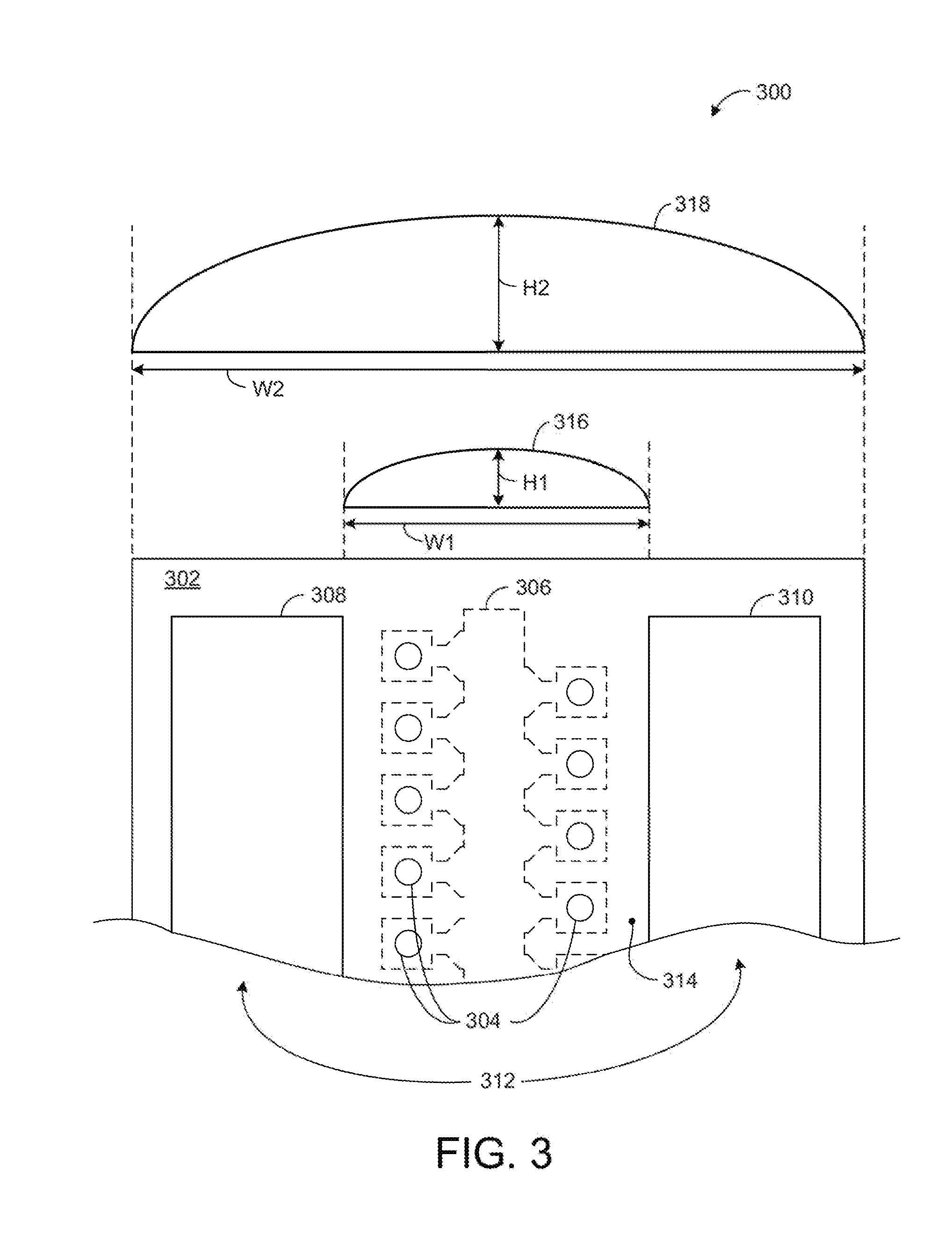
[0013]Methods and apparatus are provided related to dispense heads. A dispense head is formed to define a plurality of fluid jetting nozzles and a surface pattern. The surface pattern is characterized by one or more voids extending inward from an outer surface of the dispense head. Fluid puddle formation during operation of the dispense head is limited in volume by way of the surface pattern. Fluid puddle limiting reduces or eliminates dispensing errors to a receiving entity, or undesirable artifacts from resulting on a printed media.

[0014]In one example, a dispense head includes a material defining a fluid-jetting nozzle. The material further defines a surface pattern spaced apart from the fluid jetting nozzle. The surface pattern is configured to limit a volume of a fluid puddle for in on an outer surface of the material during operation.

[0015]In another example, a fluid dispensing apparatus includes a dispense head configured to eject fluid through a plurality of nozz...


PUM

PropertyMeasurementUnit
volumeaaaaaaaaaa
depthaaaaaaaaaa
depth-wise dimensionaaaaaaaaaa

Abstract

Methods and apparatus are provided related to fluid dispensing heads. A dispense head is formed to define a plurality of fluid jetting nozzles and a surface pattern. The surface pattern is characterized by one or more voids extending inward from an outer surface of the dispense head. Fluid puddle formation during operation of the dispense head is limited in volume by way of the surface pattern. Fluid puddle limiting reduces or eliminates dispensing errors to an entity, undesirable artifacts from resulting on a printed media, or similar problems.

Description

BACKGROUND[0001]Ink jetting printers, laboratory equipment and other devices eject fluid from nozzles so as to form images on media, deposit fluid into receptacles of a wellplate, or the like. Puddling of fluid sometimes results on an outer surface of such an entity during normal operations. Incomplete dispensing into wellplates or streaks, spots or other undesirable artifacts on a printed media can result if such puddles achieve sufficient volume. The present teachings address the foregoing and related concerns.BRIEF DESCRIPTION OF THE DRAWINGS[0002]The present embodiments will now be described, by way of example, with reference to the accompanying drawings, in which:[0003]FIG. 1 is a plan view of a dispense head according to one example of the present teachings;[0004]FIG. 2 is a schematic view of a dispense head according to another example;[0005]FIG. 3 depicts a dispense head operating scenario according to another example:[0006]FIG. 4 is an isometric-like view of a portion of a ...

Claims


Application Information

Patent Timeline
Patent Type & Authority Applications(United States)
IPC IPC(8): B05B1/28B41J2/16
CPCB41J2/16B05B1/28B41J2/1404Y10T29/49401B01L3/0268B01L2200/0605B01L2200/14B01L2300/0829B01L2300/161B05B1/02B05B1/185B41J2/005
Inventor STRAND, THOMAS R.NIELSEN, JEFFREY A.FEINN, JAMESLEIGH, STAN E.
Owner HEWLETT PACKARD DEV CO LP
Why Eureka
Try Eureka