Collapsible batting cage

a batting cage and collapse technology, applied in the field of enclosure structures, can solve the problems of inability to move to desirable locations, inconvenient positioning, high cost of operation and use, etc., and achieve the effect of increasing or decreasing the hanging distance of the ball

Inactive Publication Date: 2014-08-07
FERRARO MICHAEL
View PDF22 Cites 5 Cited by
  • Summary
  • Abstract
  • Description
  • Claims
  • Application Information

AI Technical Summary

Benefits of technology

[0008]In a specific aspect of the present invention, the ball assembly includes a line having an end connected to the ball, and a free end. A holder is carried by the truss structure and receives the line therethrough to allow the ball to hang downwardly from one side of the canopy structure. The free end of the line is removably attachable to the canopy structure, wherein the line can be adjusted through the holder, increasing or decreasing a hanging distance of the ball.

Problems solved by technology

While very effective in aiding an individual to practice batting, they can be inconveniently located and expensive to operate and use.
Another problem with conventional batting cages is that they are static, requiring the batter to come to them, and cannot be moved to desirable locations at will.

Method used


Image

  • Collapsible batting cage
  • Collapsible batting cage
  • Collapsible batting cage

Examples


Embodiment Construction

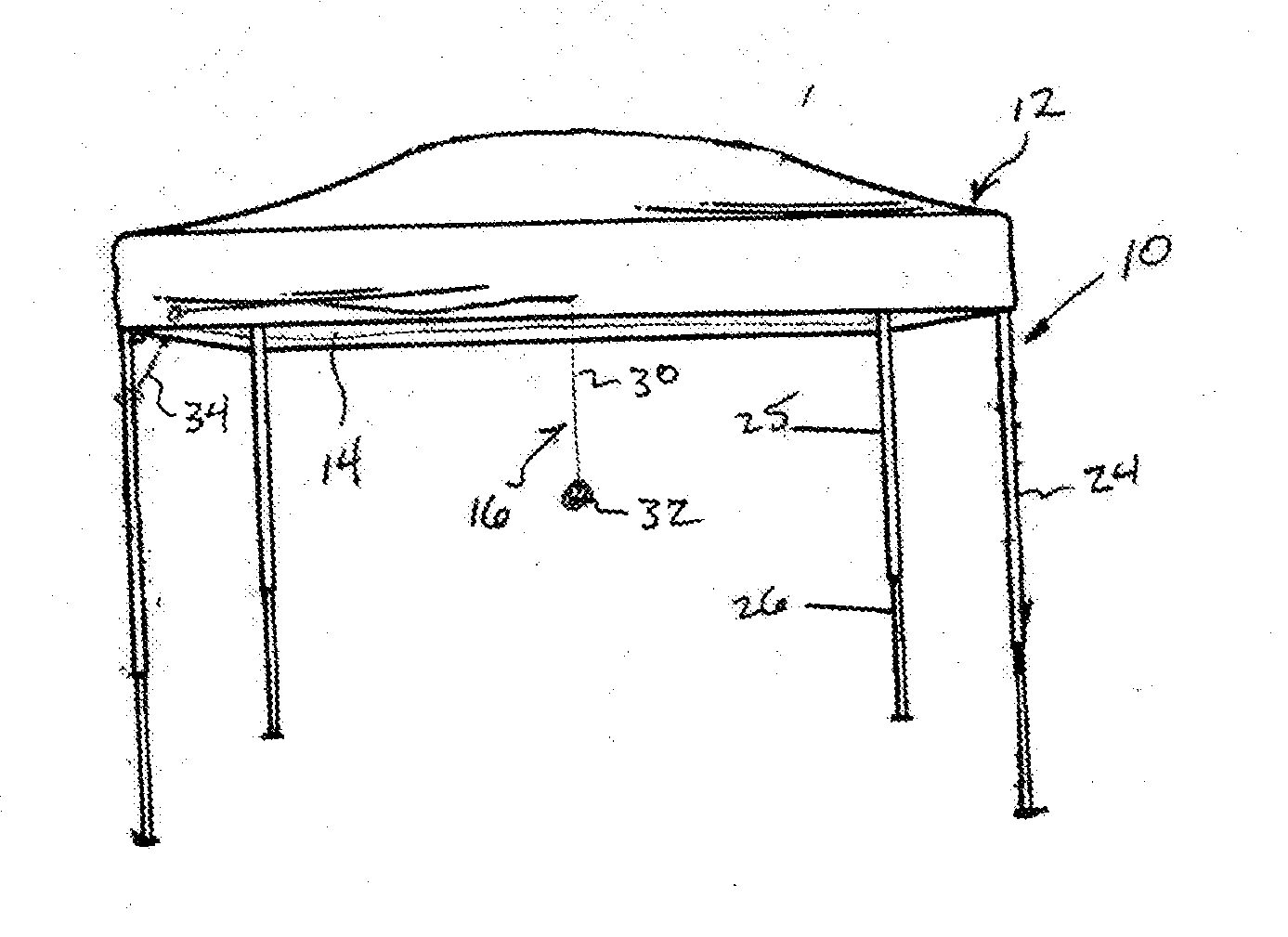
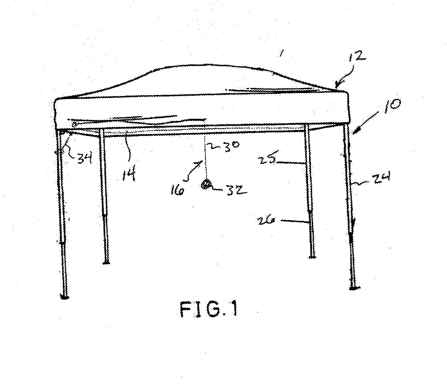
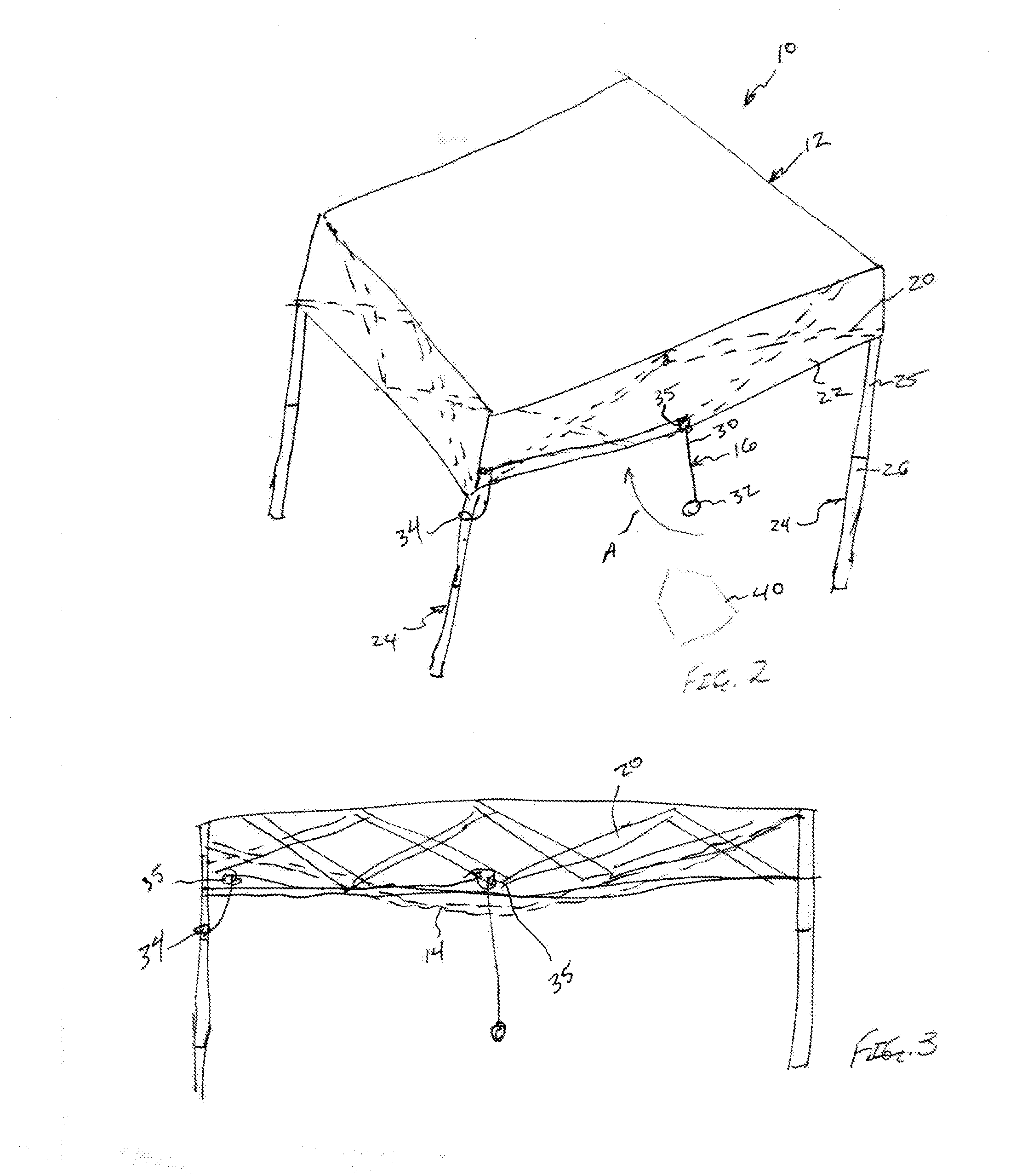
[0013]Turning now to the drawings in which like reference characters indicate corresponding elements throughout the several views, attention is directed to FIGS. 1 and 2 which illustrates a collapsible batting cage according to the present invention, generally designated 10. Batting cage 10 includes a canopy structure 12, a ball stop 14, and a ball assembly 16. Canopy structure 12 includes a collapsible truss framework 20, generally square or rectangular in shape, and supporting an overlying canopy 22. Extendable legs 24 depend downwardly from corners of truss framework 20 and each have an upper portion 25 coupled to truss framework 20 at a corner thereof and a lower portion 26 telescopingly coupled to upper portion 25 for supporting truss framework 20 and canopy 22 above a surface. Canopy structure 12 is movable between a collapsed configuration and an erected configuration. Canopy structure 12 is not described in further detail, but a canopy structure similar to that disclosed in ...


PUM


Abstract

A collapsible batting cage is provided with a collapsible canopy structure including a collapsible truss framework supporting an overlying canopy and extendable legs depend downwardly from the truss framework. A ball stop is supported by the truss framework, underlies the canopy and is spaced apart therefrom. A ball assembly having a ball is coupled to the collapsible canopy structure so as to present the ball at a batting height and permit contact between the ball and the ball stop when struck.

Description

CROSS-REFERENCE TO RELATED APPLICATION [0001]This application is a non-provisional utility application of currently pending U.S. Provisional Application Ser. No. 61 / 760,309, filed 4 Feb. 2013.FIELD OF THE INVENTION [0002]This invention relates to enclosure structures.[0003]More particularly, the present invention relates to batting cages.BACKGROUND OF THE INVENTION[0004]Enclosures, frequently referred to as batting cages, are well known in the art. These enclosures permit an individual to practice hitting a baseball or softball while limiting the distance or direction the ball can travel. The hit ball is generally stopped using a barrier. Batting cages can be very large enclosures in which the ball is delivered to a batter using a pitching machine, an in which the ball can fly essentially unimpeded, being limited only in specific direction or great ranges. Other batting cages can be smaller, simply being large enough to allow a pitching machine to deliver a ball from the appropriate...

Claims


Application Information

Patent Timeline
Patent Type & Authority Applications(United States)
IPC IPC(8): A63B71/02
CPCA63B71/022A63B69/0002A63B69/0075A63B69/0079A63B71/02A63B71/023A63B2069/0008A63B2210/50A63B2225/093
Inventor FERRARO, MICHAEL
Owner FERRARO MICHAEL
Why Eureka
Try Eureka