Adjustable operator worm gear drive with robust bearing surfaces

a worm gear drive and bearing surface technology, applied in the field of casement window operators, can solve the problems of limited durability, undue stress and strain on the operator assembly, limited force or thrust that the operator assembly is capable of withstanding, etc., and achieve the effect of increasing or decreasing the distance of the bearing disc from the threaded post and facilitating rotation

Active Publication Date: 2015-07-09
INTERLOCK USA
View PDF14 Cites 5 Cited by
  • Summary
  • Abstract
  • Description
  • Claims
  • Application Information

AI Technical Summary

Benefits of technology

[0028]The method further includes a vertical adjustment assembly comprising: an adjustment screw and bearing disc, the bearing disc having a knurled surface to facilitate rotation within a cavity of a housing base; a cylindrical bearing having an outer diameter approximately equal to, and insertable within, an aperture within an attachment portion of the actuator arm; and a threaded post within the cover plate for receiving the adjustment screw; such that the rotating of the vertical adjustment assembly includes contacting the knurled surface of the bearing disc and turning the bearing disc about a center axis, thereby increasing or decreasing the distance of the bearing disc from the threaded post.

Problems solved by technology

One issue with this type of design is the limited amount of force or thrust that the operator assembly is capable of withstanding.
This limited durability is especially evident under adverse environmental conditions such as high winds acting on an opened sash, which causes undue stress and strain on the operator assembly.
Additionally, thrust forces associated with opening a partially blocked sash, or a sash that for other reasons remains reluctant to open, are amplified and present undue stress on the housing and worm gear drive that can cause breakage or undue degradation over a short period of time.
A second issue with this type of design is the inability to make adjustments to the operator assembly, and particularly the operator assembly actuator arm, during or after installation.
Although there is a type of adjustment to the arm, this adjustment is not designed to be made after installation, and there is no attempt in this prior art to provide an adjustment screw with bottom bearing surface made of a hardened material to support the thrust loads on the worm gear downward.

Method used


Image

  • Adjustable operator worm gear drive with robust bearing surfaces
  • Adjustable operator worm gear drive with robust bearing surfaces
  • Adjustable operator worm gear drive with robust bearing surfaces

Examples


Embodiment Construction

)

[0039]In describing the preferred embodiment of the present invention, reference will be made herein to FIGS. 1-9 of the drawings in which like numerals refer to like features of the invention.

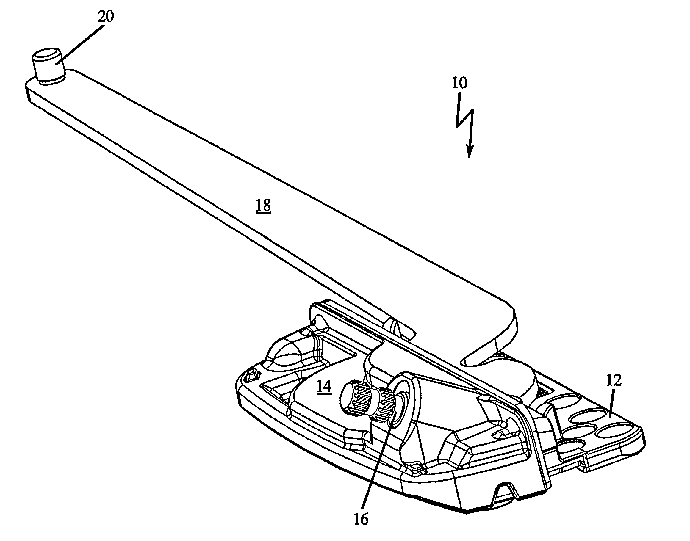
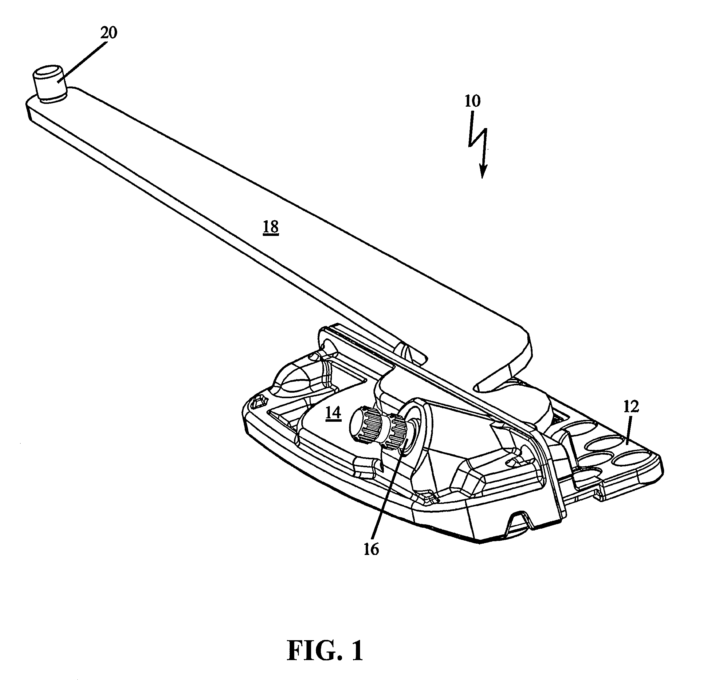
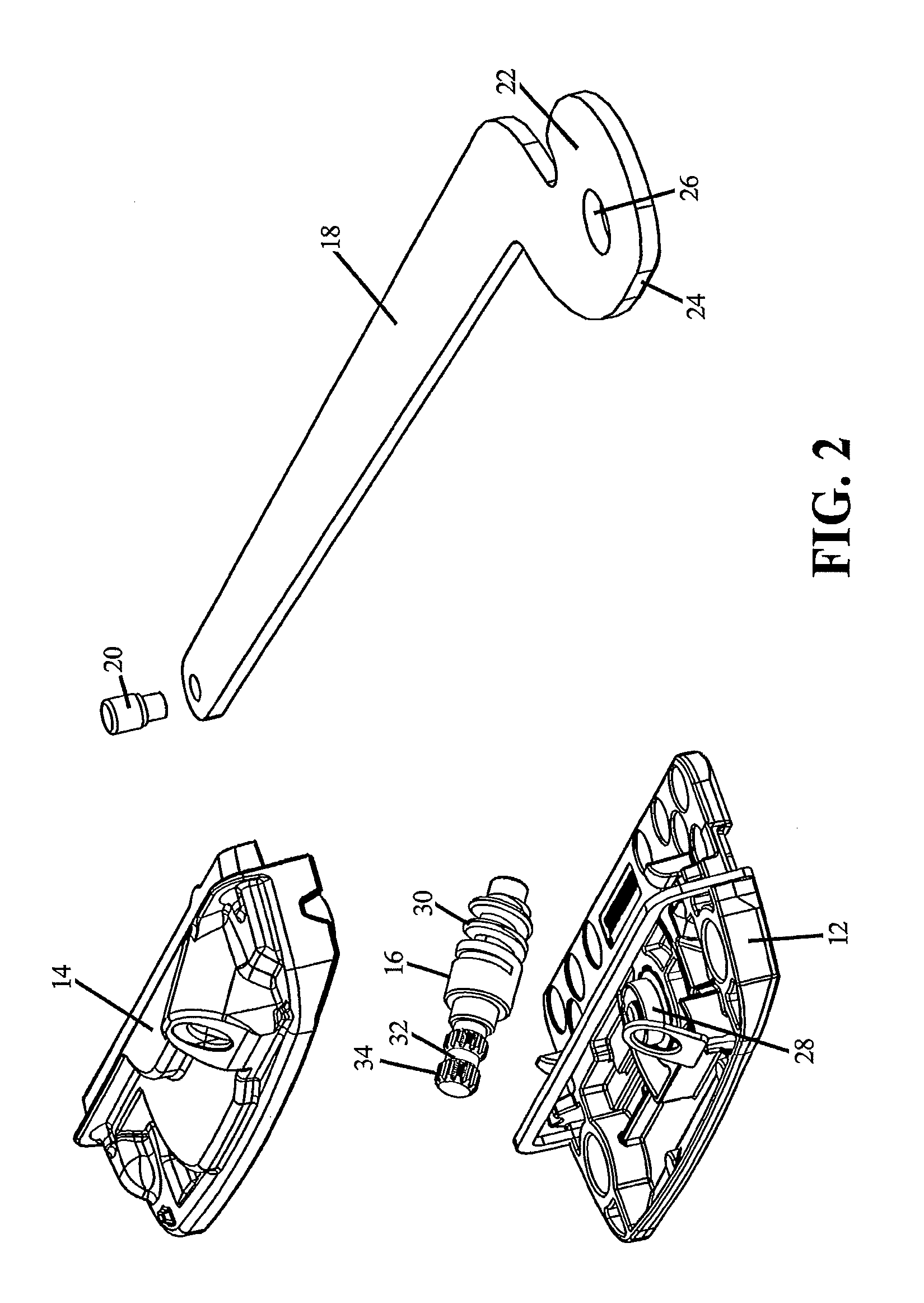
[0040]FIG. 1 depicts a casement window operator assembly 10 according to the present invention. The basic elements of operator assembly 10 are a housing base 12 and a housing cover plate 14, which enclose a worm drive assembly 16 that drives a partially enclosed actuator arm 18. Actuator arm 18 works in conjunction with a bar hinge that extends and retracts a sash (not shown). The bar hinge is able to be fitted to either the top or bottom of the window, though generally it will be positioned at the bottom of the window. The window operator assembly 10 is mounted to the frame of the window.

[0041]Actuator arm 18 is pivotally coupled to housing base 12 via a pivot or bearing. The other end of actuator arm 18 is pivotally coupled by a pivot or bearing 20 to a sash mounting plate (not shown). This...


PUM


Abstract

A worm gear drive operator having immovable flat thrust bearing surfaces at each end of a worm gear drive for absorbing thrust forces and keeping direct mechanical rotational forces away from the cover plate and housing base during rotation of the worm gear drive. The worm gear drive operator assembly is capable of vertical adjustment of the actuator arm while providing thrust support. A threaded post about which rests a bearing for the actuator arm, and is secured in place by an adjustment screw received within a threaded post on the cover plate.

Description

BACKGROUND OF THE INVENTION[0001]1. Field of the Invention[0002]This invention relates to casement window operators of the type in which a pivotally mounted window controlling lever is actuated by a crank or electric motor operated worm gear drive, and specifically to one having a more robust design for supporting thrust loads. More specifically, the worm gear drive operator is designed with thrust bearing components at each end of a worm gear drive to remove mechanical rotating surfaces from interaction with the housing base or cover plate, while absorbing the rotational thrust of the device. The invention further relates to a vertically adjustable actuator arm, where the adjustment may be made in-situ after installation utilizing a threaded post about which rests a bearing for the actuator arm on a hardened steel plate for thrust load support, and which is secured in place by an adjustment screw received within the threaded post.[0003]2. Description of Related Art[0004]A casement ...

Claims


Application Information

Patent Timeline
Patent Type & Authority Applications(United States)
IPC IPC(8): E05F11/34F16H1/16
CPCF16H1/16E05F11/34Y10T74/18792
Inventor MINTER, PETER J.FULLENWIDER, MARC W.
Owner INTERLOCK USA
Why Eureka
Try Eureka