Flat panel electronic display arrangement for attachment to a transparent base structure

a technology of electronic display and transparent base structure, which is applied in the field of electronic display arrangement for attachment to transparent base structure, can solve the problems of inability to clearly or at all see images, significantly reduced quality, and inability to address inventions

Inactive Publication Date: 2014-08-21
ONYX DISPLAY MEDIA
View PDF0 Cites 78 Cited by
  • Summary
  • Abstract
  • Description
  • Claims
  • Application Information

AI Technical Summary

Problems solved by technology

However, the quality is significantly diminished when the fridge is stocked with goods.
Physical objects in the background seem to hinder the display to such an extent that the images cannot be seen clearly or at all.
However, these inventions do not address the abovementioned drawbacks and still do not provide high quality display characteristics when a fridge is in use under everyday usage conditions, e.g. cold and stocked and they do not display the ability to work without the cavity of a fridge, which they are using to bounce the light from the fridge, in order to light up the images on the transparent LCD.

Method used


Image

  • Flat panel electronic display arrangement for attachment to a transparent base structure
  • Flat panel electronic display arrangement for attachment to a transparent base structure
  • Flat panel electronic display arrangement for attachment to a transparent base structure

Examples


first embodiment

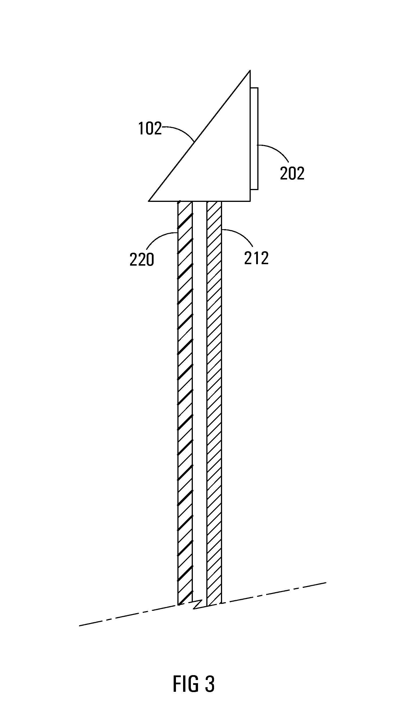
[0062]FIGS. 3-5 also illustrates strata of the display portion 104. FIG. 3 illustrates a first embodiment in which the display arrangement 100 includes an transparent LCD layer 212 operable to display electronic images based on a video input and a switchable light source layer 220 arranged parallel to and operatively behind a majority of the transparent LCD layer 212. The light source layer 220 may be switchable to vary an intensity of light emitted therefrom. It is also at least partially light-transmissive.

[0063]The transparent LCD layer 212 employs LCD-based display technology. There are many LCD variants which may be practicable, such as IPS, PLS, TFT, etc. and the specific technology used is not germane to this disclosure, provided that the transparent LCD layer 212 is transparent or at least translucent. The transparent LCD layer 212 is operable to display electronic images / video based on an electronic video input (e.g. HDMI, DVI, VGA, etc.).

[0064]The light source layer 220 is...

second embodiment

[0065]FIG. 4 illustrates a second embodiment including the transparent LCD and light source layers 212, 220 of FIG. 3 and also including a switchable film layer 214 arranged behind the light source layer 220. Instead of being a discrete layer 214 as illustrated, the switchable film layer 214 may be applied (e.g. adhesively) to another layer, e.g. the back of the light source layer 220.

[0066]Opacity of the switchable film 214 is electronically controlled, depending on defined opacity criteria, to be variable from transparent to opaque. The switchable film 214 can thus present an opaque backing for the transparent LCD layer 212 or a mere clear window interfering minimally or not at all with light transmission.

third embodiment

[0067]FIG. 5 illustrates a third embodiment including the layers 212, 220, 214 of FIG. 4 and also including protective layers 216 arranged on outer sides of the remaining layers 212, 220, 214. The protective layers 216 are clear and may be of glass (e.g. hardened glass), polycarbonate (e.g. Gorilla™ glass) or of a polymer (e.g. acrylic / Plexiglas™). Instead of two protective layers 216 as illustrated, there may be only one, on an inner or outer side. The protective layers 216 serve as a physical barrier to protect the more delicate transparent LCD layer 212 and may also serve as a thermal barrier to help provide a measure of insulation from the cold within the fridge, and from any warmth generated by the layers 212, 202, 214.

[0068]It may be possible or even desirable to include a touch sensitive layer (not illustrated) operable to receive a capacitive touch input from a person (in similar fashion to the touch screen of a smart phone or tablet). If included, the touch sensitive layer ...


PUM

PropertyMeasurementUnit
transparentaaaaaaaaaa
opacityaaaaaaaaaa
poweraaaaaaaaaa

Abstract

A flat panel electronic display arrangement for attachment to a transparent base structure (e.g. a fridge door). The electronic display arrangement including a transparent LCD layer operable to display electronic images based on a video input, a light source layer arranged parallel to and operatively behind a majority of the transparent LCD layer. The light source layer being operable to emit light directly behind the majority of the transparent LCD layer and being at least partially light-transmissive. The electronic display arrangement including a frame or housing to which the transparent LCD layer and light source layer are attached, a controller operable to control the video input to the transparent LCD layer and the operation of the light source layer, and a mounting arrangement operable to mount the frame to the transparent base structure.

Description

RELATED APPLICATIONS[0001]The application claims priority from South African Application No. 2013 / 01368, filed on Feb. 21, 2013, the entire contents of which is hereby expressly incorporated herein by reference.FIELD OF INVENTION[0002]This invention relates broadly to electronic display screens and more specifically to a flat panel electronic display arrangement for attachment to a transparent base structure such as a glass door or window.BACKGROUND OF INVENTION[0003]The Applicant is aware of current efforts to attach or integrate electronic displays (e.g. LCD panels) into glass doors and especially into refrigerator (simply “fridge”) doors. The Applicant has observed that an LCD flat panel can be fixed to one side (either outside or inside) of a glass fridge door, especially those of the type often found in shops and supermarkets. When the fridge is empty and the internal fridge light is on, the images / display from the flat panel seem fairly good. However, the quality is significan...

Claims


Application Information

Patent Timeline
Patent Type & Authority Applications(United States)
IPC IPC(8): G02F1/1333G02F1/13
CPCG02F1/1313G02F1/133308A47F3/0434E06B2009/2464F25D23/02F25D2400/361F25D2700/04G02F1/133615G02F2203/01
Inventor VENTURAS, PANAYIOTISCOUDOUNARIS, ANDREW GREGORY
Owner ONYX DISPLAY MEDIA
Why Eureka
Try Eureka