
Artificial horse leg stand

a leg stand and artificial technology, applied in the field of artificial leg stands, can solve the problems of affecting the stability of the horse, affecting the performance of the horse, and requiring considerable skill for the farmer, and achieve the effect of improving stability and simple structur

Inactive Publication Date: 2014-08-21
CHAMPAGNE WESLEY JON
View PDF0 Cites 0 Cited by
  • Summary
  • Abstract
  • Description
  • Claims
  • Application Information

AI Technical Summary

Benefits of technology

The present invention is a farrier training system that addresses all of the deficiencies of prior art inventions. It includes an artificial horse leg stand system with a planar base, an outer tubular member, an inner tubular member, an angle bracket, a rotating trunion, and a securing fixture. The system also includes at least one lower shock mount, a dual-acting gas shock absorber, and a rotation locking mechanism. The invention provides a more stable and secure training system for farriers.

Problems solved by technology

As horses tend to weigh 1000 lbs. or more and may have difficult personalities, the attachment of a horseshoe to the hoof of a horse without injury to the horse or the farrier is a task requiring considerable skill.
Further complicating the work is the fact that the hoof must usually be trimmed to mate properly with the horseshoe and the shoe is typically attached with nails.
If the nails are driven too deeply into the hoof, delicate capillaries may be injured and bleeding, discomfort and even infection may result.
Recent legislation has severely limited such practices.

Method used


Image

  • Artificial horse leg stand
  • Artificial horse leg stand
  • Artificial horse leg stand

Examples


Embodiment Construction

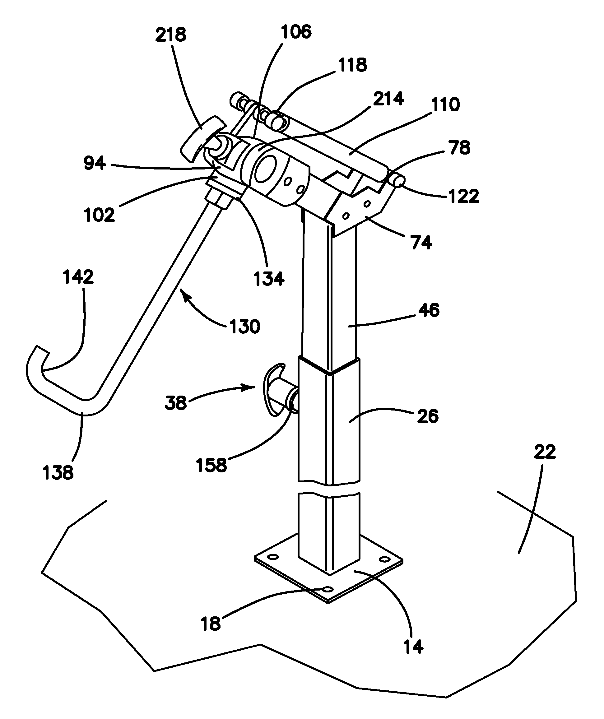
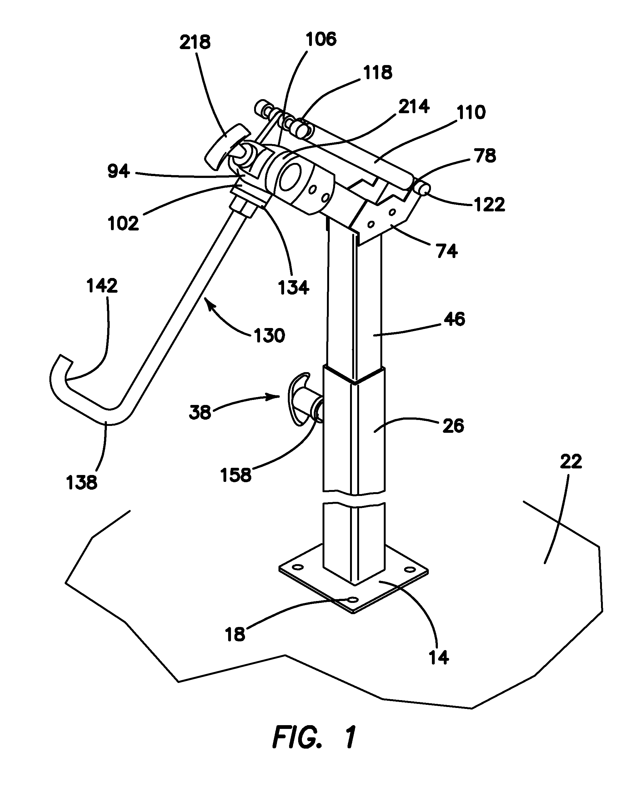
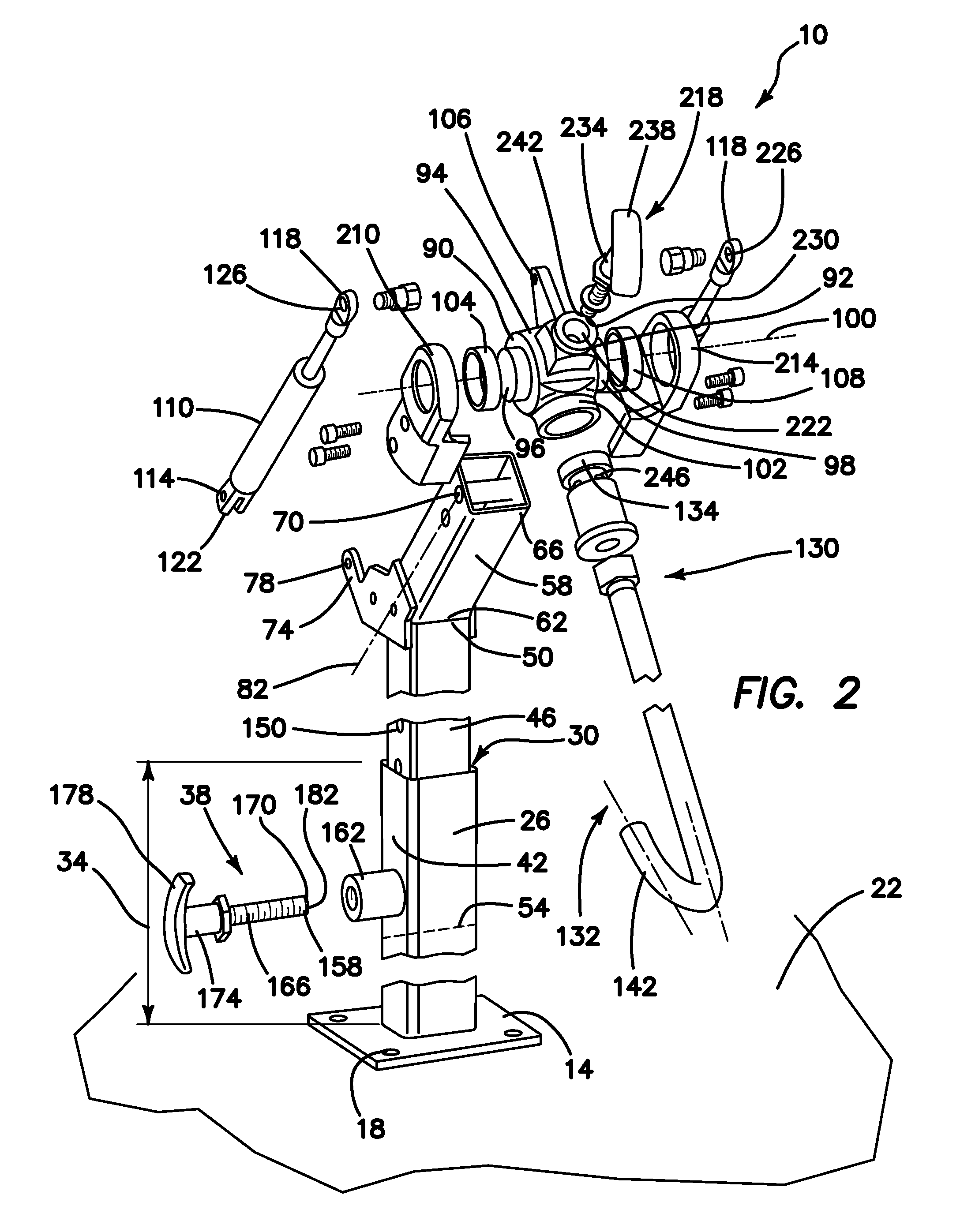
[0032](1) FIGS. 1-4 illustrate an artificial horse leg stand system 10 providing the desired features that may be constructed from the following components. As illustrated in FIGS. 1-3, planar base 14 is provided. The base 14 has at least one fitting 18 for securing the base 14 to a surface 22. An outer tubular member 26 is provided. The outer member 26 has an interior cavity 30, is orthogonally attached to the base 14 and extends upwardly from the base 14 for a first predetermined distance 34. The outer member 26 has a height adjusting mechanism 38. The mechanism 38 is orthogonally attached to an exterior surface 42 of the outer member 26 and at least partially extends into the interior cavity 30. An inner tubular member 46 is provided. The inner member 46 has a first end 50, a second end 54 and is sized and shaped to fit slidably within the interior cavity 30. An angle bracket 58 is provided. The bracket 58 has a proximal end 62, a distal end 66, is attached at the proximal end 62...


PUM


Abstract

An artificial horse leg stand includes a planar base, outer and inner tubular members providing height adjustment with an angled bracket at an upper end of the inner member. The bracket has a mounting feature located adjacent the distal end for attachment of a rotating trunion and a lower shock mount at the proximate end. The trunion has cylindrical positioning features extending outwardly from first and second sides. An attachment fixtures is located orthogonally to a horizontal axis of the trunion. The trunion has an upper shock mount spaced from the attachment fixture. The trunion is rotatably attached by the cylindrical positioning features to the mounting feature. Dual-acting gas shock absorbers are rotatably attached to the upper and lower shock mounts. A securing fixture is attached to the attachment fixture at the first end and has a mounting feature at the second end for attachment to an artificial horse leg.

Description

RELATED APPLICATION[0001]The instant application claims priority from U.S. PCT Application Serial Number PCT / US13 / 36443 filed Apr. 12, 2013 and U.S. Provisional Application Ser. No. 61 / 706,593 filed Sep. 27, 2012.FIELD OF INVENTION[0002]This invention relates to the field of training systems, and more specifically to an artificial leg stand for use with a training system for teaching farriers to make and attach horseshoes to the hooves of horses.BACKGROUND OF THE INVENTION[0003]The horse's hoof is composed of five major regions: the wall, the sole, the frog, the periople and the white line. The hoof grows as a result of cell division in the outer horn-producing cell layer of the sensitive structures of the hoof, namely the perioplic ring, the coronary band and the sensitive laminae. This process may be affected by many factors such as diet, stresses, injuries and diseases. In such cases, a distorted hoof is often produced. The hoof wall is of primary concern. It bears most of the ho...

Claims


Application Information

Patent Timeline
Patent Type & Authority Applications(United States)
IPC IPC(8): A01L11/00
CPCA01L11/00A01K15/00
Inventor CHAMPAGNE, WESLEY JON
Owner CHAMPAGNE WESLEY JON
Learn More