
Device, system and method for blood vessel imaging and marking

a blood vessel and imaging technology, applied in the field of devices, systems and methods for blood vessel imaging, can solve the problems of limiting the efficiency of devices and affecting the cost effectiveness of systems, and achieve the effect of easy finding the required blood vessel

Active Publication Date: 2014-08-21
RAHUM UZI
View PDF8 Cites 37 Cited by
  • Summary
  • Abstract
  • Description
  • Claims
  • Application Information

AI Technical Summary

Benefits of technology

The present invention is about a system and method for non-invasively identifying and locating blood vessels in a person's body. This means that accurate identification of a blood vessel can be done in a way that is repeatable and can be done offline. This means that a practitioner does not need to be in front of the imaging device in real-time, which makes the procedure more efficient and flexible. The method involves using a target area image, which is printed onto a scanned area or associated substrate. This allows for offline viewing and access to the blood vessel. The system can also include marks that make it easy to find the required blood vessel and apply a blood vessel measurement technique. This technology eliminates the need for real-time diagnosis, making the procedure safer and more efficient.

Problems solved by technology

Accordingly, the current vein viewing system are limited in that they do not provide for en-mass use, rather a single system must be used per each extraction process, therein greatly limiting the efficiency of the device.
This limitation influences the cost effectiveness of the system and its return of investment form economical view point.

Method used


Image

  • Device, system and method for blood vessel imaging and marking
  • Device, system and method for blood vessel imaging and marking
  • Device, system and method for blood vessel imaging and marking

Examples


Embodiment Construction

[0054]The principles and operation of the present invention may be better understood with reference to the drawings and the accompanying description.

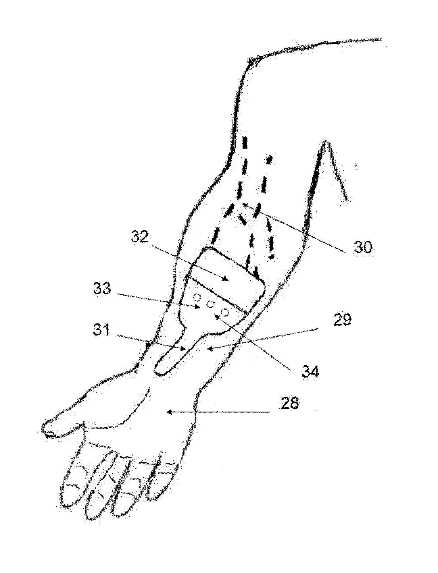
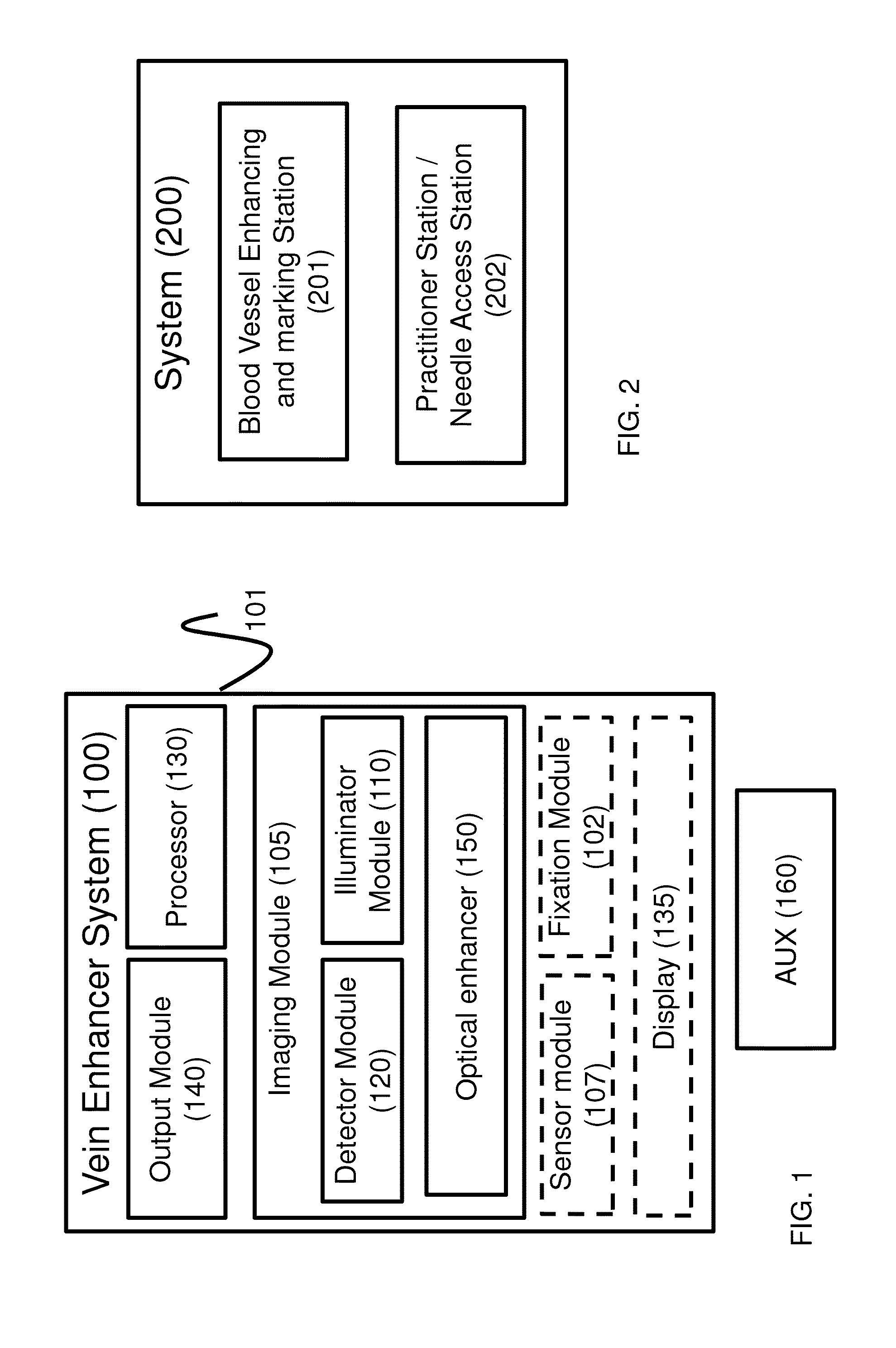
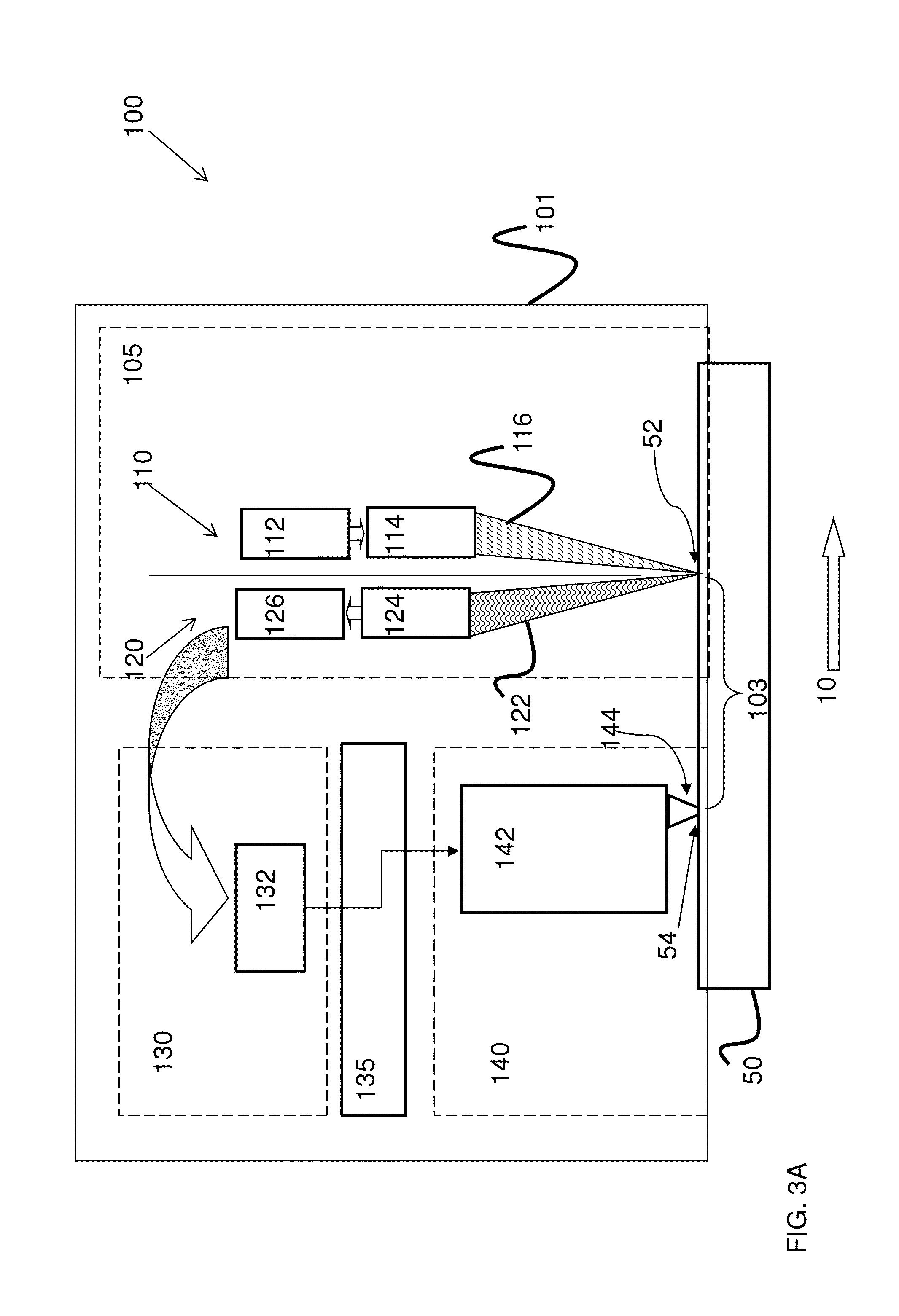
[0055]The following figure reference labels are used throughout the description to refer to similarly functioning components are used throughout the specification hereinbelow.[0056]10 target area scanning direction;[0057]15 forearm target area;[0058]16 un-scanned portion of target area;[0059]18 housing;[0060]22 rail[0061]26 rail track system[0062]27 auxiliary fixation device;[0063]50 target area;[0064]20,52 scanning site / imaging line;[0065]54 printing site;[0066]17, 55 detected blood vessel;[0067]57 detected optimal position;[0068]103 scanning distance;[0069]100, 200 blood vessel enhancing imaging system;[0070]101 enhancer housing;[0071]105 scanner / image capture module;[0072]19, 110 illumination unit;[0073]112 illumination source and / or generator[0074]19,114 illumination head;[0075]116 incident light;[0076]120 detector unit;[0077]122 re...


PUM


Abstract

The present invention relates to a device, system and a method for blood vessel imaging, detection, and marking and in particular, to such a device, system and method in which an optical enhancers are utilized to increase the accuracy and quality of the process for detecting a blood vessel.

Description

RELATED APPLICATIONS[0001]This application is a Continuation in Part of, and claims priority from, PCT Application No. PCT / IL2012 / 050303, filed on Aug. 12, 2012, which claims priority from U.S. Provisional Application No. 61 / 523,369, filed on Aug. 14, 2011, and also claims priority from U.S. Provisional Application No. 61 / 764,283, filed on Feb. 13, 2013, all of which are hereby incorporated by reference in its entirety.FIELD OF THE INVENTION[0002]The present invention relates to a device, system and a method for blood vessel imaging, detection, and marking and in particular, to such a device, system and method in which optical enhancers are utilized to increase the accuracy and quality of the process for detecting a blood vessel.BACKGROUND OF THE INVENTION[0003]Access to the blood stream via a needle is perhaps the most common procedure administered by healthcare professionals, and may be referred to as Blood Vessel Medical Treatment (hereinafter referred to as ‘BVMT’). Access to th...

Claims


Application Information

Patent Timeline
IPC IPC(8): A61B5/00
CPCA61B5/0059A61B5/0075
Inventor RAHUM, UZI
Owner RAHUM UZI
Learn More