Field paver connector and restraining system

a technology of connectors and supporting systems, applied in the direction of building repairs, ceilings, flooring, etc., can solve the problems of affecting the safety of workers, causing damage to the surface of elevated surfaces, and causing a potentially dangerous environment requiring subsequent repair, displacement or buckling of other surface tiles

Active Publication Date: 2014-08-28
UNITED CONSTR PROD LLC
View PDF21 Cites 22 Cited by
  • Summary
  • Abstract
  • Description
  • Claims
  • Application Information

AI Technical Summary

Benefits of technology

[0019]In one arrangement, the disposing step may include first securing a first plurality of the mounting elements adjacent a first end of the restraining members to the top surfaces of first support pedestals of the first portion of the plurality of support pedestals, and second securing a second plurality of the mounting elements adjacent an opposing second end of the restraining members to the top surfaces of second support pedestals of the first portion of the plurality of support pedestals, where each of the first support pedestals is adjacent one of the second support pedestals. For instance, the first ends of a first plurality of the restraining members and the second ends of a second plurality of the restraining members may be secured over common ones of the first portion of the plurality of support pedestals.

Problems solved by technology

One problem associated with some support structures for elevated surfaces is that the surface tiles or other members making up the elevated surfaces are sometimes susceptible to movement due to pressure differences above and below the tiles, such as from strong winds blowing across the surface tiles.
More specifically, wind can sometimes generate uplift forces, particularly around a perimeter of an elevated building surface, that can dislodge surface tiles and thereby create a possibly dangerous environment requiring subsequent repair.
In this case, uplift forces from wind are often greatest near the corners of the elevated building surface (e.g., where adjacent parapet sections meet) and can dislodge surface tiles which may eventually lead to displacement or buckling of other surface tiles.

Method used


Image

  • Field paver connector and restraining system
  • Field paver connector and restraining system
  • Field paver connector and restraining system

Examples


Embodiment Construction

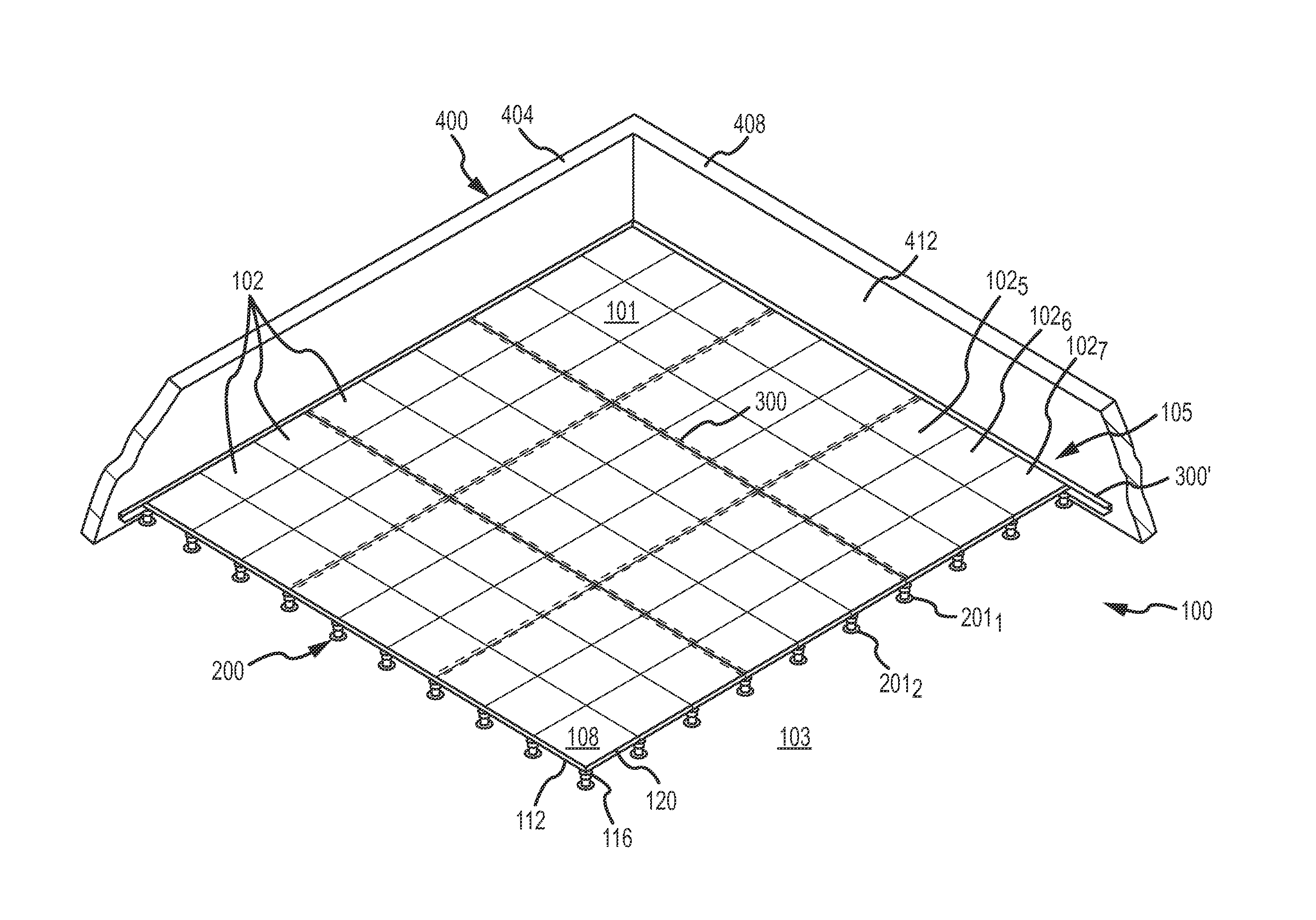
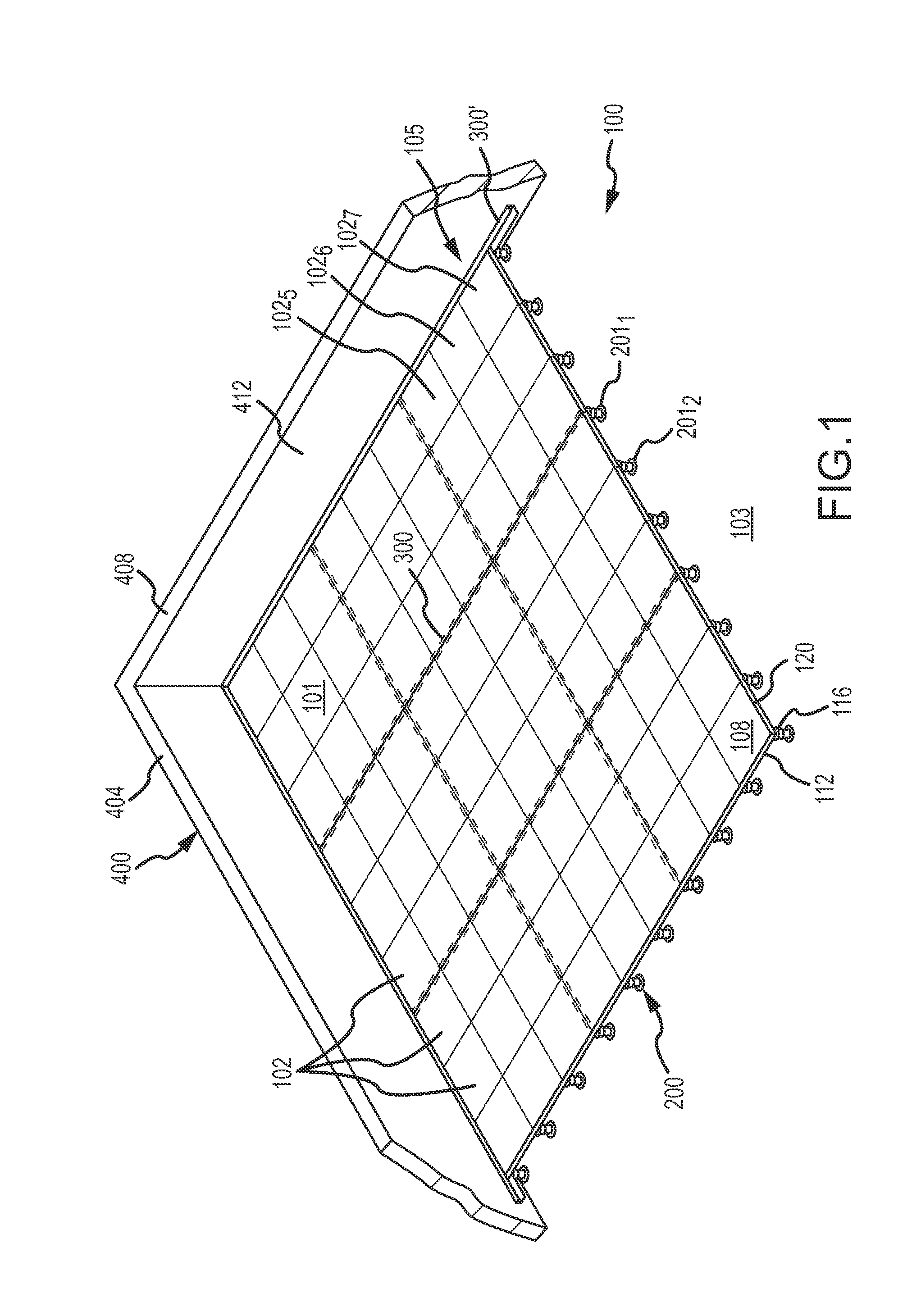
[0039]FIG. 1 illustrates a portion of an elevated building surface assembly 100 according to one embodiment that includes an elevated building surface 101 formed from a plurality of building surface components such as surface tiles 102 that are elevated above a fixed surface 103 by a support structure 200. Each surface tile 102 may broadly include generally opposing top and bottom surfaces 108, 112, one or more corner portions 116, and one or more outer edge segments 120 disposed between adjacent corner portions 116. The support structure 200 includes a plurality of spaced-apart support pedestals 201 (e.g., in any appropriate configuration, such as a plurality of rows and columns of support pedestals 201) supporting the surface tiles 102 and a plurality of elongate restraining members 300, 300′ (e.g., surface tile connectors), the restraining members 300 being shown in phantom lines in FIG. 1.

[0040]As will be discussed in more detail herein, each restraining member 300, 300′ is conf...


PUM


Abstract

An elevated building surface assembly including a plurality of surface tiles, a plurality of support pedestals disposed in spaced-apart relation on a fixed surface and having a support plate with a top surface operatively supporting the surface tiles in horizontally spaced-apart relation, and a plurality of elongate restraining members configured to restrict movement of the surface tile(s) in directions away from first and second adjacent support pedestals and/or relative to one or more adjacent surface tiles to advantageously limit movement or displacement of the surface tile(s) that may otherwise occur due to uplift forces (e.g., generated by winds and/or the like).

Description

BACKGROUND OF THE INVENTION[0001]1. Field of the Invention[0002]This invention relates to the field of support structures for supporting and restraining an elevated surface above a fixed surface, such as support structures to elevate surface tiles for elevated floors, decks and walkways.[0003]2. Description of Related Art[0004]Elevated building surfaces such as elevated floors, decks, terraces and walkways are desirable in many environments. One common system for creating such surfaces includes a plurality of surface tiles, such as concrete tiles (e.g., pavers), stone tiles or wood tiles, and a plurality of spaced-apart support pedestals upon which the tiles are placed to be supported above a fixed surface. For example, in outdoor applications, the surface may be elevated above a fixed surface by the support pedestals to promote drainage, to provide a level structural surface for walking, and / or to prevent deterioration of or damage to the surface tiles. The pedestals can have a fix...

Claims


Application Information

Patent Timeline
Patent Type & Authority Applications(United States)
IPC IPC(8): E04F15/024
CPCE04F15/02464E04F15/02452E04D11/005E04D11/007E04F15/02044E04F15/02405E04F15/02447E04F15/02458E04F15/0247E04F15/02494E04F2015/02061E04F2015/02122H02G3/285
Inventor KUGLER, WILLIAM E.KNIGHT, III, STEPHEN J.
Owner UNITED CONSTR PROD LLC
Why Eureka
Try Eureka