Knee support

a knee joint and support technology, applied in the field of knee support, can solve the problems that the inner rotation and outer rotation of the knee joint cannot be actually restrained or corrected, and achieve the effect of effective correction or alleviation

Inactive Publication Date: 2014-08-28
NIPPON SIGMAX
View PDF4 Cites 1 Cited by
  • Summary
  • Abstract
  • Description
  • Claims
  • Application Information

AI Technical Summary

Benefits of technology

[0011]According to the present invention, the projection provided in the support main body or the strap is, when wearing, engaged with the shinbone, the distal adhesion of the semimembranous muscle or the distal adhesion of the biceps femoris muscle along the strap pulling direction at the contact region so as to serve as a stopper for the support main body, even if the strap is wound around and fixed while being pulled in the direction opposite to the inner rotation or outer rotation direction. Therefore, the support main body is not displaced in the strap pulling direction of the strap, thereby further certainly restraining the inner rotation or the outer rotation. As a result of that, the inner rotation or the outer rotation of the knee joint is effectively corrected or alleviated by wearing the knee support of the present invention.

Problems solved by technology

Therefore, in some conventional knee supports, an inner rotation and outer rotation of a knee joint may not be actually restrained or corrected.

Method used


Image

  • Knee support
  • Knee support
  • Knee support

Examples


first embodiment

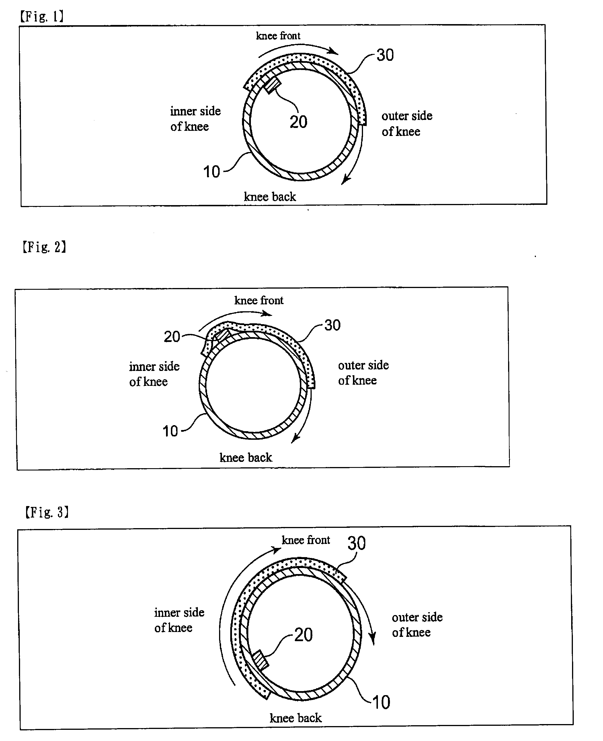
[0023]FIG. 1 is a schematic cross-sectional explanatory drawing for showing a support for restraining / correcting an inner rotation of the right leg according to the present invention.

[0024]In FIG. 1, 10 is a support main body. Its form is not limited as long as it can cover the knee joint. It may either be of a close type, an open type or a semi close type. Moreover, its material may be of any kind.

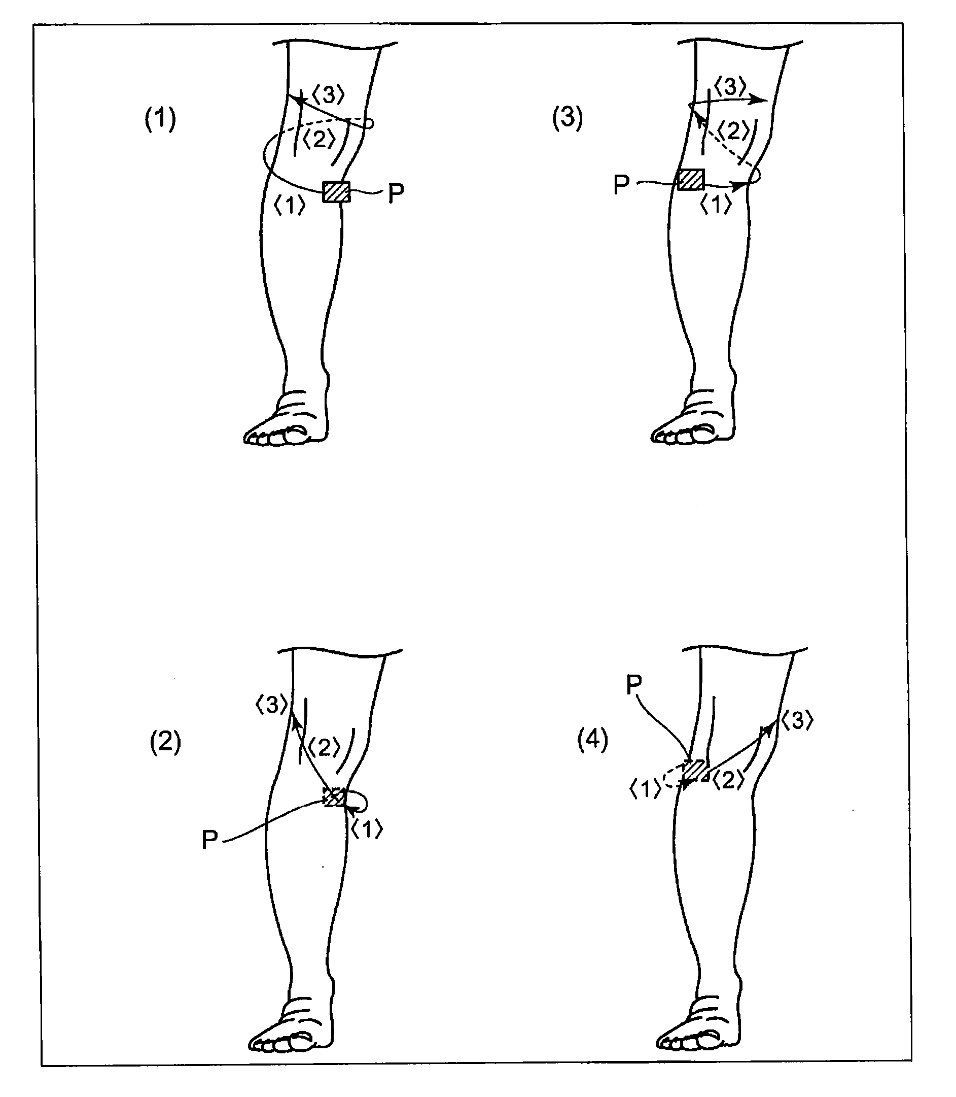
[0025]An inner surface of the support main body 10 is provided with a projection 20 to be engaged with the shinbone below the knee from the inner side to the outer side direction along the pulling direction of a strap 30 to be described later, when wearing, at a region to be contacted with the inner side of the shinbone below the knee. In particular, as shown in FIG. 9(1), it is preferable to provide the same at an inner position by 0.5 to 3 cm from a center of a tibial tuberosity of the shinbone in terms of obtaining an effective engaging function with respect to the shinbone.

[0026]The f...

second embodiment

[0031]FIG. 2 is a schematic cross-sectional explanatory drawing for showing a support for restraining / correcting an inner rotation of the right leg according to the present invention.

[0032]The second embodiment has the same component as that of the first embodiment shown in FIG. 1 except that the projection 20 is provided on the inner surface of the strap 30 instead of the support main body 10.

[0033]In the second embodiment, the projection 20 is contacted with the inner side of the shinbone via the support main body 10 when wearing.

third embodiment

[0034]FIG. 3 is a schematic cross-sectional explanatory drawing for showing a support for restraining / correcting an inner rotation of the right leg according to the present invention.

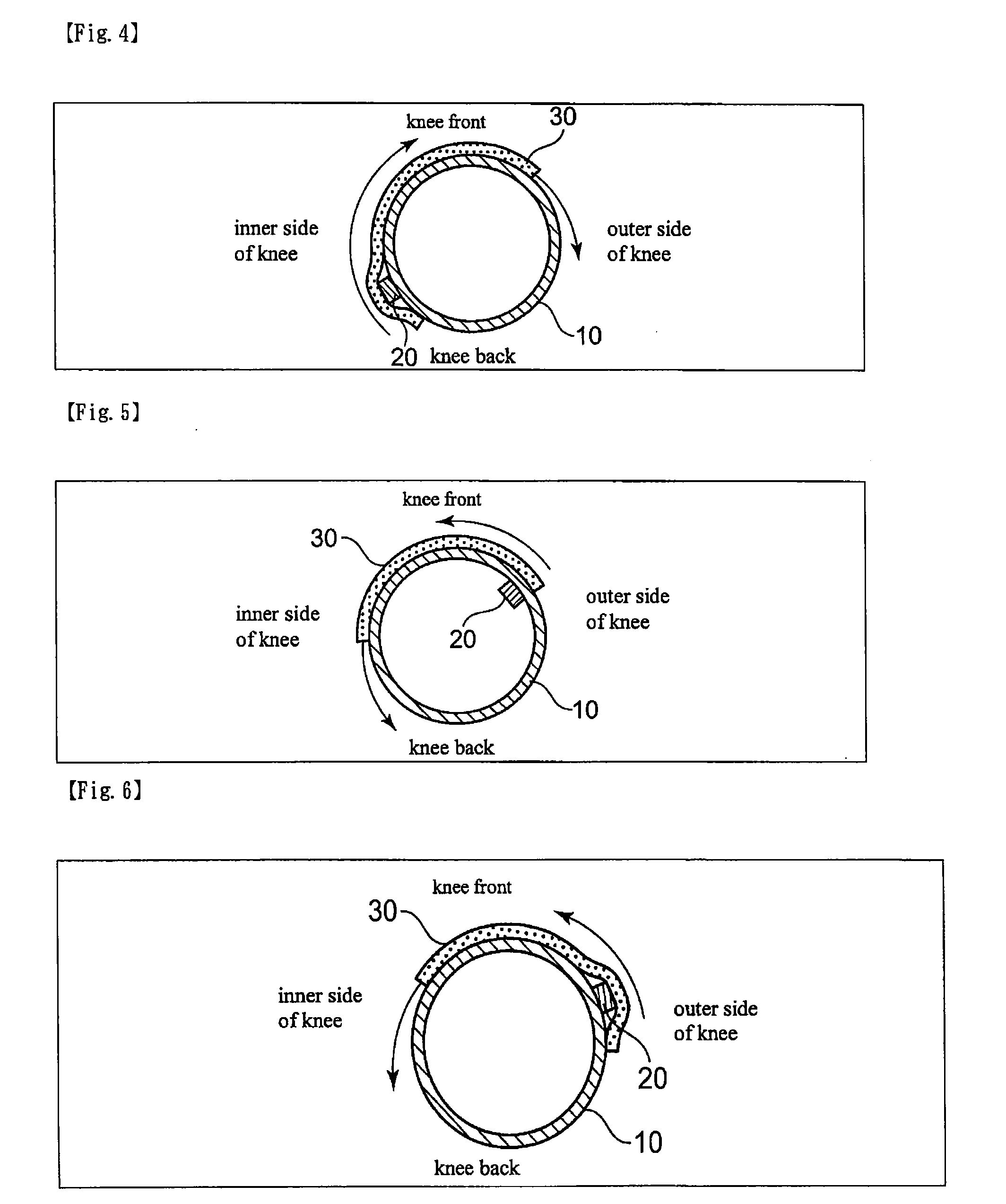
[0035]In FIG. 3, the inner surface of the support main body 10 is provided with a projection 20 to be engaged with the gastrocnemius muscle below the knee from the outer side to the inner side direction along the pulling direction of a strap 30, when wearing, at a portion to be contacted with the gastrocnemius muscle below the knee. In particular, as shown in FIG. 9(2), it is preferable to provide the same in the vicinity of a distal adhesion of the semimembranous muscle in terms of obtaining an effective engaging function with respect to the distal adhesion of the semimembranous muscle.

[0036]In this embodiment, as in the case of the first embodiment shown in FIG. 1, the strap 30 is wound around and attached on the outer surface of the support main body 10 helically while being pulled in the direction o...


PUM


Abstract

Provided is a knee support capable of correcting / alleviating an inner rotation or outer rotation of a knee joint.A knee support comprising a support main body for covering a knee joint, and a strap to be wound around and attached on an outer surface of the support main body helically while being pulled in the direction opposite to an inner rotation direction of the joint, wherein a projection to be contacted with an inner side of a shinbone below the knee when wearing is provided on the inner surface of the support main body or the inner surface of the strap.

Description

FIELD OF THE INVENTION[0001]The present invention relates to a knee support capable of correcting or alleviating inner rotation or outer rotation of a knee joint.BACKGROUND OF THE INVENTION[0002]Various forms of knee support have conventionally been reported, and all of them are for obtaining an appropriate supporting and fixing power and facilitating smooth movement of the joint by appropriately combining members with different expansion and contraction ratios or providing a pad thereto (see Patent Document 1).[0003]Therefore, in some conventional knee supports, an inner rotation and outer rotation of a knee joint may not be actually restrained or corrected.CITATION LISTPatent Document[0004]Patent Document 1: JP 2003-88544 ASUMMARY OF THE INVENTIONProblem to be Solved by the Invention[0005]The present invention has been achieved in view of the conventional situation as mentioned above, and its objective is to provide a knee support capable of restraining or correcting an inner rota...

Claims


Application Information

Patent Timeline
Patent Type & Authority Applications(United States)
IPC IPC(8): A61F5/01
CPCA61F5/0123A61F5/0106A61F13/061A61F2005/0176
Inventor YAMAMOTO, NAOTAKA
Owner NIPPON SIGMAX
Why Eureka
Try Eureka