Device for positioning platen roller

Inactive Publication Date: 2014-09-11
TSC AUTO TECH
View PDF5 Cites 0 Cited by
  • Summary
  • Abstract
  • Description
  • Claims
  • Application Information

AI Technical Summary

Benefits of technology

[0017]Therefore, when a user moves the first clip and the second clip toward the first moving direction and the second moving direction respectively with the first elastic element, the elasticity generated when stretching the first elastic element helps the first clip an

Problems solved by technology

In prior art, positioning a platen roller in a positioning room is very convenient, but when the weight of carriers on the platen roller decreases, the platen roller ten

Method used


Image

  • Device for positioning platen roller
  • Device for positioning platen roller
  • Device for positioning platen roller

Examples


Example

[0026]The present invention relates to a device for positioning a platen roller. In the following description, numerous details are set forth in order to provide a thorough understanding of the present invention. It will be appreciated by one skilled in the art that variations of these specific details are possible while still achieving the results of the present invention. In other instance, well-known components are not described in detail in order not to unnecessarily obscure the present invention.

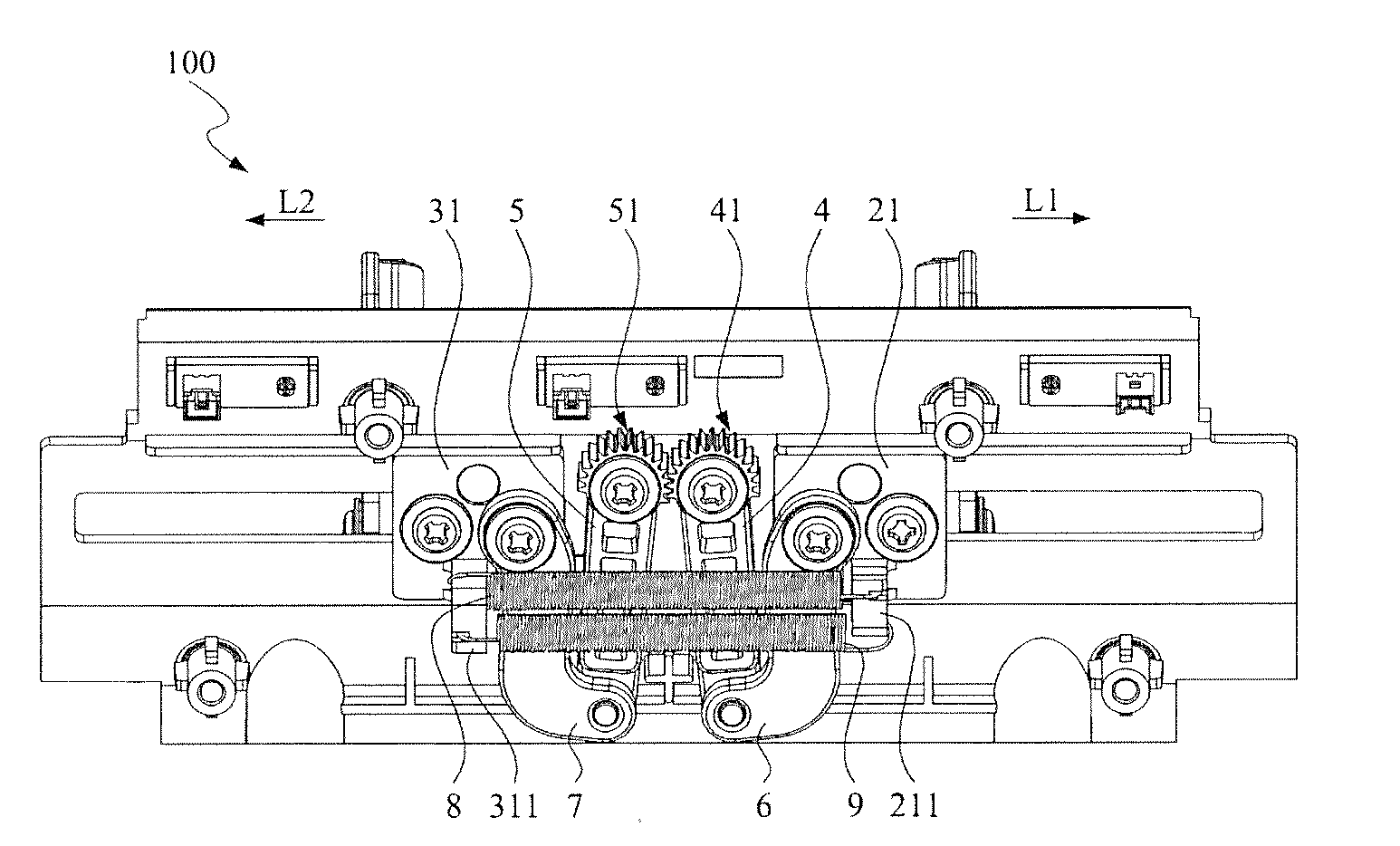
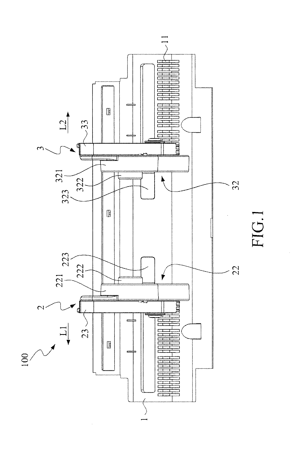
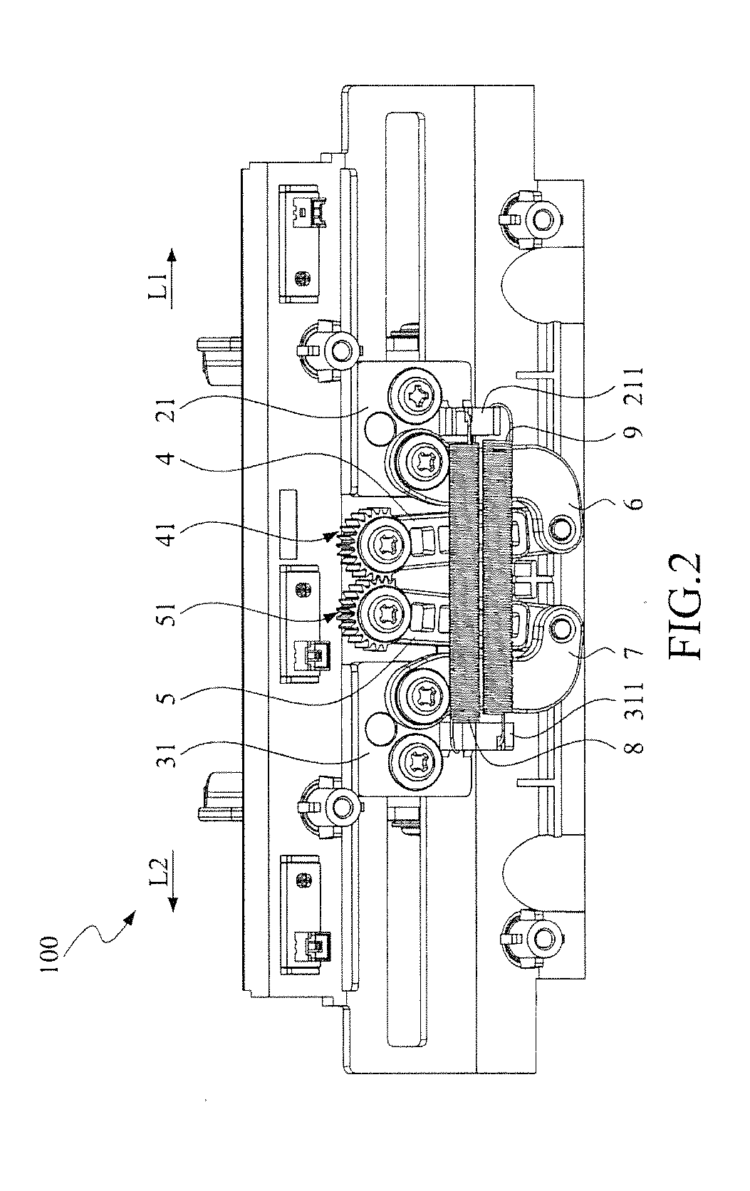
[0027]Refer to FIGS. 1, 2, 3 and 4; FIG. 1 is a schematic view showing the front of a device for positioning a platen roller according to an embodiment of the present invention; FIG. 2 is a schematic view showing the back of the device for positioning a platen roller according to the embodiment of the present invention; FIG. 3 is a three-dimensional view of a first clip according to the embodiment of the present invention; FIG. 4 is a three-dimensional view showing another side of the f...


PUM


Abstract

A device for positioning a platen roller is provided, the device including a body, a first clip, a second clip, a first rotating arm, a second rotating arm, a first linkage, a second linkage and a first elastic element. The first clip and the second clip are disposed movably on the body; the first and the second rotating arm are disposed rotatably on the body; the first linkage couples the first rotating arm and the first clip; the second linkage couples the second rotating arm and the second clip; the first elastic element connects the first clip and the second clip, wherein when the first clip and the second clip move toward a first moving direction and a second moving direction respectively, the first elastic element provides elasticity so that the first clip and the second clip restore.

Description

BACKGROUND OF THE INVENTION[0001]1. Field of the Invention[0002]The present invention relates to a device for positioning a platen roller and more particularly, relates to a device positioning a platen roller via an elasticity generated by an elastic element.[0003]2. Description[0004]Printers are everywhere in our daily life, especially printers printing tags, barcodes, or thermal printers printing receipts. Platen rollers are widely used in these printers for providing papers, carbon sheets or ink ribbons. A platen roller is usually placed inside a positioning room with two ends or assembled and fixed on clips directly.[0005]Although positioning a platen roller in a positioning room is very convenient, when the weight of carriers on the platen roller decreases, the platen roller tends to be moved since it is positioned by its weight; on the other hand, although positioning a platen roller by assembling is stable, the operation is more difficult and inconvenient.[0006]Thus, a device...

Claims


Application Information

Patent Timeline
IPC IPC(8): B41J11/04
CPCB41J11/04
Inventor HO, MING-CHUN
Owner TSC AUTO TECH
Why Eureka
Try Eureka