
Projector

a projector and screen technology, applied in the field of projectors, can solve the problems of disadvantageous increase in the number of components of the projector, and achieve the effect of suppressing the increase in the number of components of the apparatus body and detecting the broken condition of the screen

Inactive Publication Date: 2014-09-11
FUNAI ELECTRIC CO LTD
View PDF0 Cites 8 Cited by
  • Summary
  • Abstract
  • Description
  • Claims
  • Application Information

AI Technical Summary

Benefits of technology

The present invention aims to address the problem of detecting screen damage in a convenient and cost-effective way. The technical effect of the invention is to provide a projector that can easily detect when the screen is broken without adding extra components to the apparatus body.

Problems solved by technology

Therefore, the number of components constituting the projector is disadvantageously increased.

Method used


Image

  • Projector
  • Projector
  • Projector

Examples


first embodiment

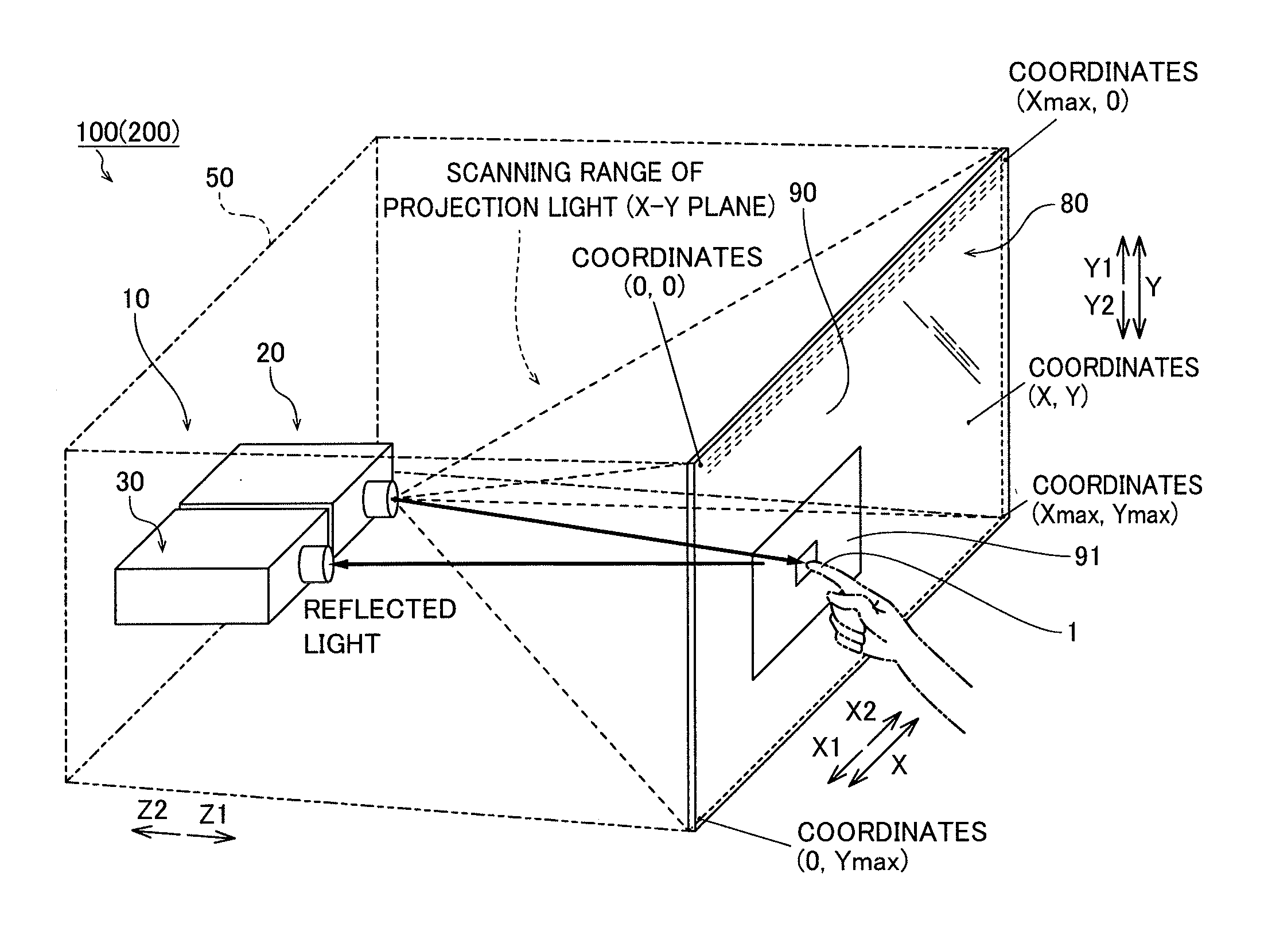
[0052]The structure of a rear projector 100 according to a first embodiment of the present invention is now described with reference to FIGS. 1 to 9. The rear projector 100 is an example of the “projector” in the present invention.

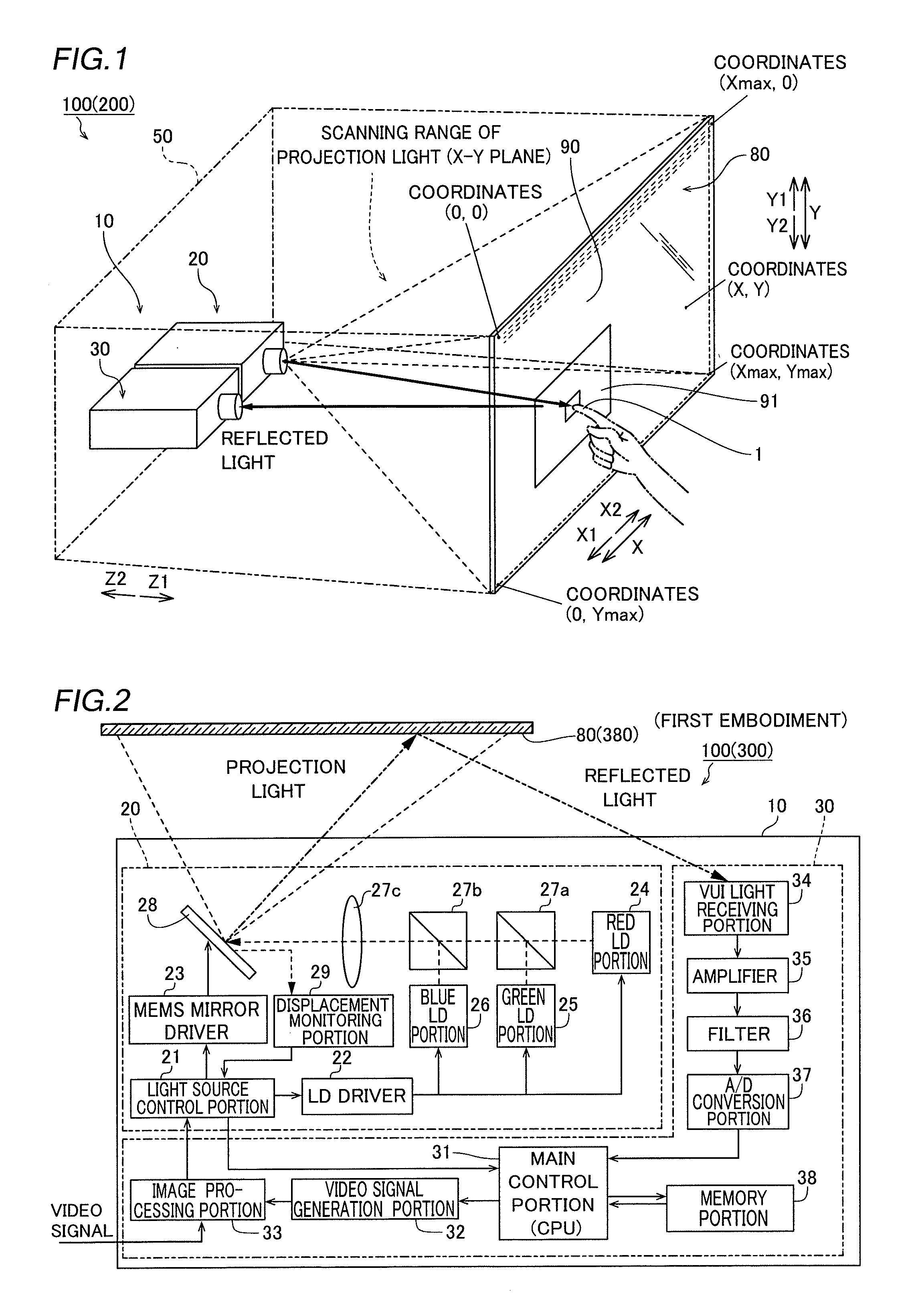
[0053]The rear projector 100 according to the first embodiment of the present invention includes an apparatus body 10 into which a projection portion 20 including a light source portion employing a semiconductor laser element is built and a transmissive screen 80 on which a laser beam scanned by the projection portion 20 of the apparatus body 10 is projected as an image (picture), as shown in FIG. 1. The apparatus body 10 is housed in a housing 50 (the outer shape is shown by a two-dot chain line), and the transmissive screen 80 is set on the front side (Z1 side) of the housing 50.

[0054]According to the first embodiment, the rear projector 100 has a virtual user interface (VUI) function. In other words, a user can operate the apparatus body 10 or perform a...

second embodiment

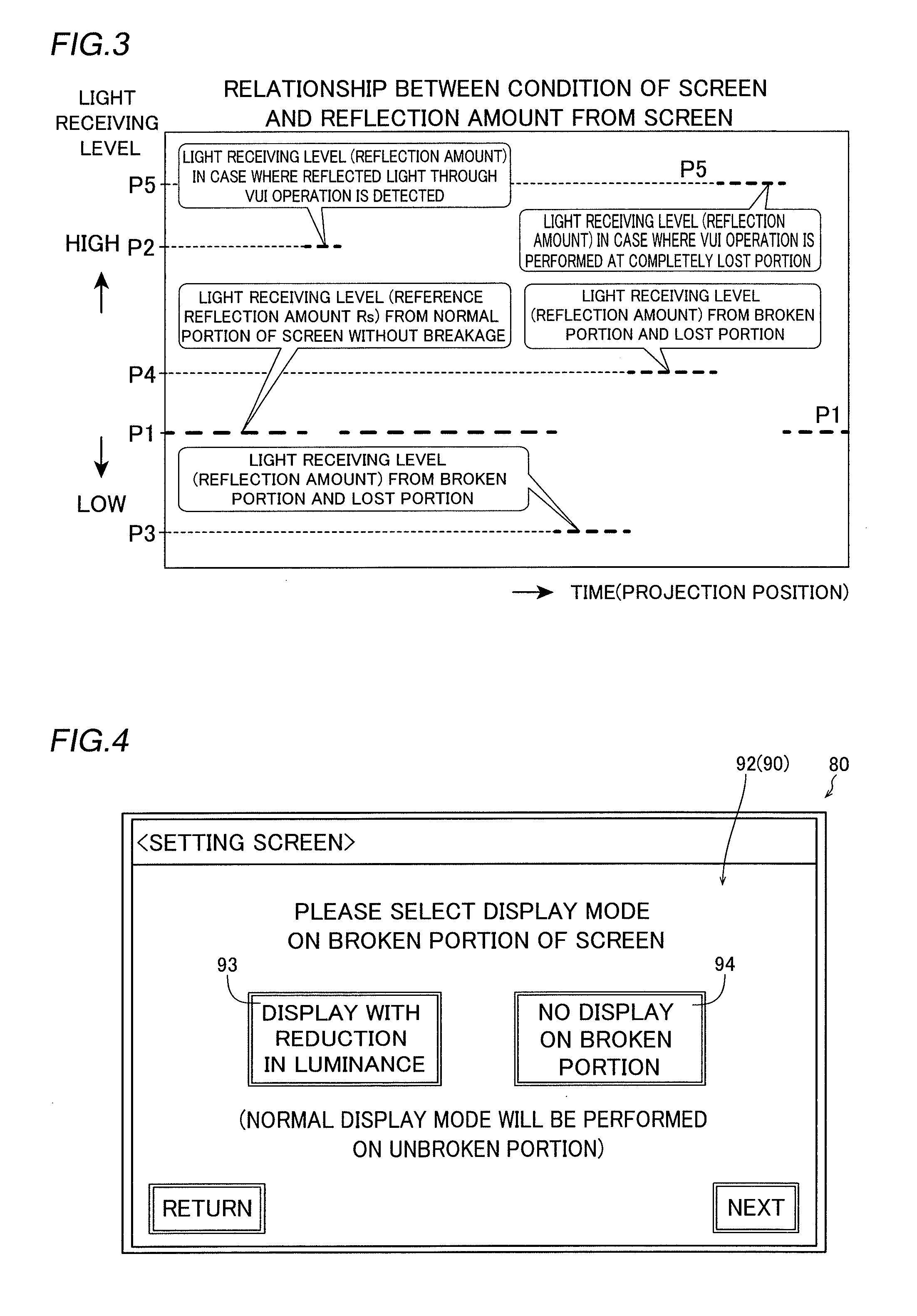
[0109]A second embodiment is now described with reference to FIGS. 10 to 12. In this second embodiment, a rear projector 200 is configured to start a “breakage detection operation mode” of a screen 80 when an apparatus body 10 detects an impact during the projection of an image 90 (picture) on the screen 80. The rear projector 200 is an example of the “projector” in the present invention. In the figure, a structure similar to that of the rear projector 100 according to the aforementioned first embodiment is denoted by the same reference numerals.

[0110]The rear projector 200 according to the second embodiment of the present invention includes an impact detecting portion 201, as shown in FIG. 10. The impact detecting portion 201 is mounted on a prescribed position in the apparatus body 10 and is electrically connected to a main control portion 231 of a VUI portion 30. The impact detecting portion 201 has a function of detecting the presence or absence of an impact externally applied t...

third embodiment

[0133]The structure of a rear projector 300 according to a third embodiment of the present invention is now described with reference to FIGS. 2, 3, 9 to 11, and 13 to 20. The rear projector 300 is an example of the “projector” in the present invention.

[0134]The rear projector 300 according to the third embodiment of the present invention includes an apparatus body 10 into which a projection portion 20 is built and a transmissive screen 380, as shown in FIG. 13. Also in the rear projector 300 (see FIG. 2), the outputs of laser beams emitted from a red LD portion 24, a green LD portion 25, and a blue LD portion 26 and the posture of a MEMS mirror 28 are varied for each pair of projection coordinates on the screen 380 on the basis of the control of an LD driver 22 and a MEMS mirror driver 23 performed by a light source control portion 21, whereby a laser beam is two-dimensionally scanned on the screen 380 for each pixel, and an image 90 of one frame is projected. The image 90 projected...


PUM


Abstract

A projector includes a projection portion projecting an image on a screen by scanning a laser beam emitted from a laser beam generation portion, a light detecting portion detecting at least the laser beam reflected by a detection object, and a control portion configured to perform control of accepting an apparatus operation on the basis of a detection result of the laser beam reflected by the detection object obtained by the light detecting portion and control of detecting the breakage of the screen on the basis of a detection result of the laser beam reflected by the screen obtained by the light detecting portion.

Description

BACKGROUND OF THE INVENTION[0001]1. Field of the Invention[0002]The present invention relates to a projector, and more particularly, it relates to a projector including a projection portion projecting an image on a screen by scanning a laser beam.[0003]2. Description of the Background Art[0004]A projection display apparatus including a projection portion projecting an image on a screen by scanning a laser beam is known in general, as disclosed in Japanese Patent Laying-Open No. 2008-180921, for example.[0005]Japanese Patent Laying-Open No. 2008-180921 discloses a projection display apparatus (projector) integrally including a housing into which a light source portion is built, having a light-shielding function and a transmissive screen arranged on the front side of the housing. In the projection display apparatus described in Japanese Patent Laying-Open No. 2008-180921, a light detector (light sensor) detecting part of image light incident on the transmissive screen, propagating int...

Claims


Application Information

Patent Timeline
Patent Type & Authority Applications(United States)
IPC IPC(8): G03B21/14
CPCG03B21/142G03B21/2033G03B21/2086H04N9/3129H04N9/3194G09G3/002G09G3/006G09G2354/00G09G2360/145G03B1/14
Inventor AKAMATSU, KENJI
Owner FUNAI ELECTRIC CO LTD
Learn More