Cooking hood LED light

a led light and cooking hood technology, applied in the field of light, can solve the problems of led lights not providing the uniform coverage mandated for commercial cooking surfaces, incandescent lights are not energy efficient, and damage to electronics

Active Publication Date: 2014-09-11
KASON IND INC
View PDF16 Cites 19 Cited by
  • Summary
  • Abstract
  • Description
  • Claims
  • Application Information

AI Technical Summary

Benefits of technology

[0005]In a preferred form of the invention an LED light for a kitchen hood comprises a housing having a top wall and side walls depending downwardly from the top wall, a light reflector assembly coupled to the housing, the light reflector assembly including a truncated four sided pyramid shape

Problems solved by technology

However, these incandescent lights are not energy efficient.
The problem is that LED lights do not provide the even coverage mandated for commercial cooking surfa

Method used


Image

  • Cooking hood LED light
  • Cooking hood LED light
  • Cooking hood LED light

Examples


Embodiment Construction

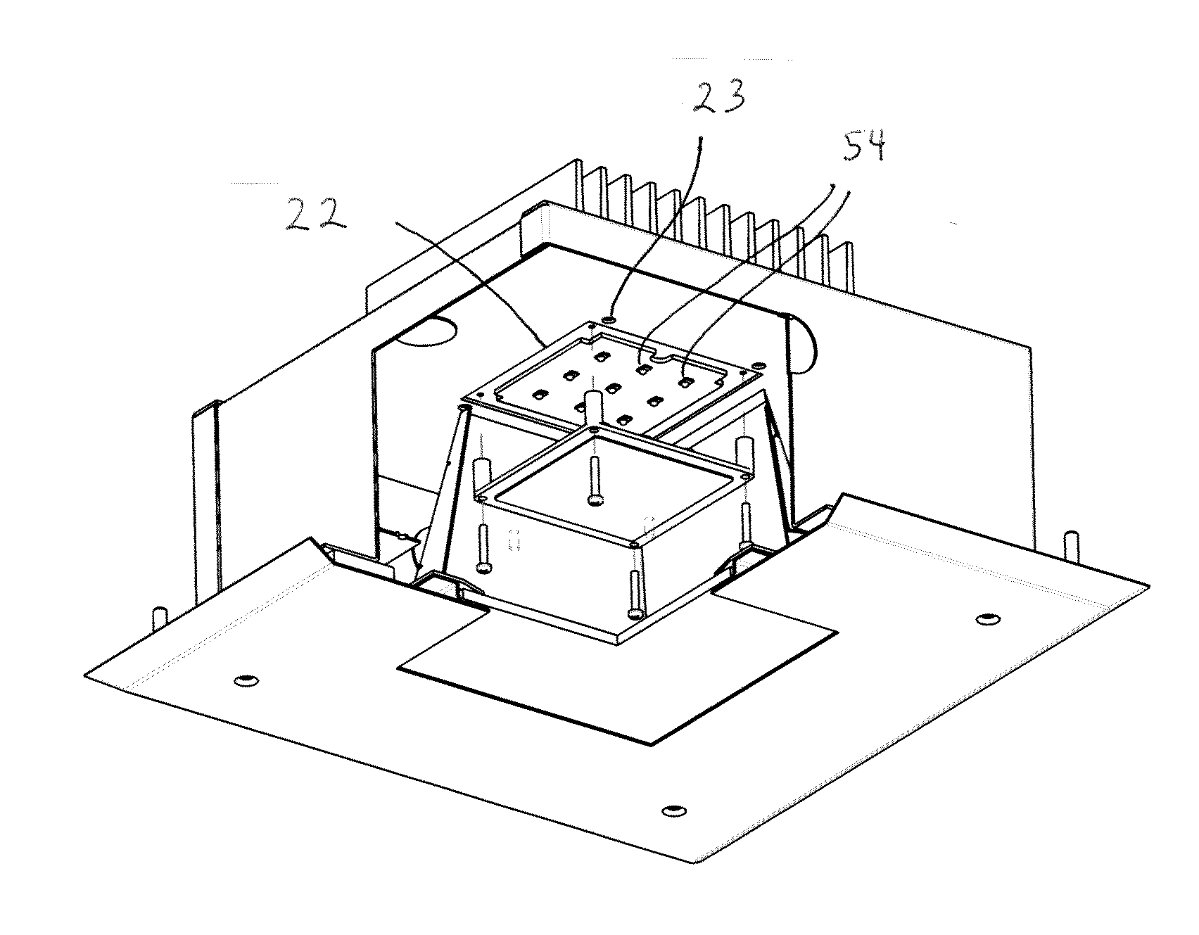
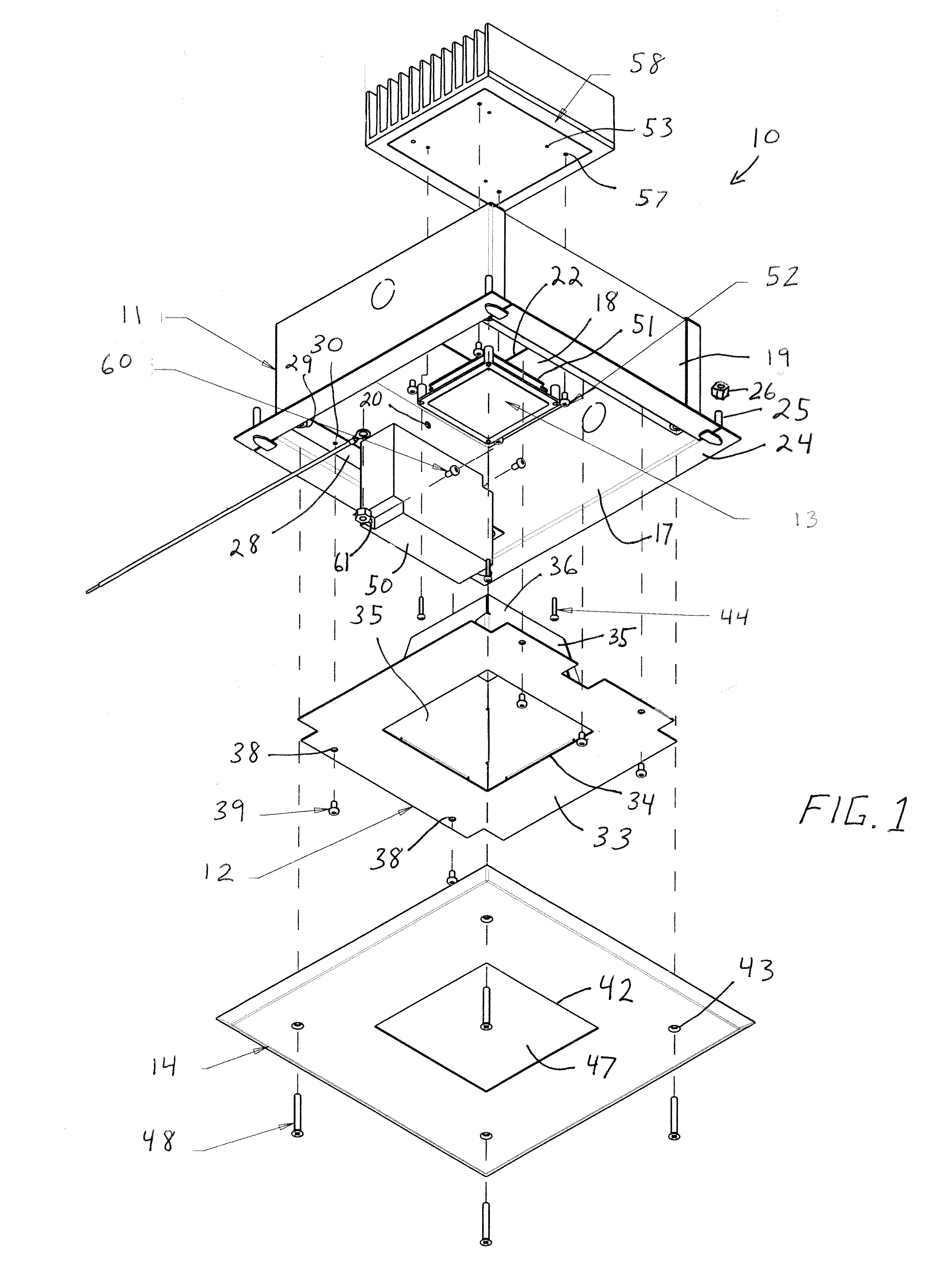
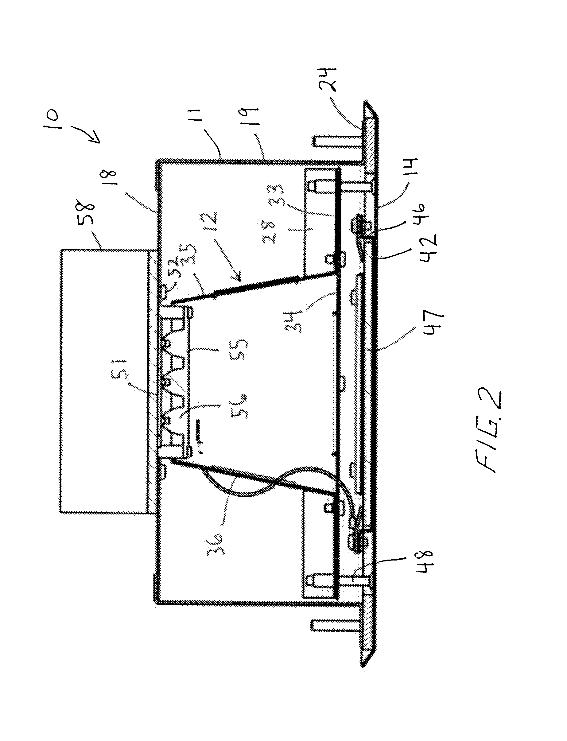
[0010]With reference next to the drawings, there is shown a cooking hood LED light 10 according to the present invention. The LED light 10 is typically mounted to a cooking hood positioned above a cooking surface. The LED light 10 includes a main housing portion, enclosure, or housing 11, a reflector assembly 12 coupled to the housing 11, an LED lighting circuit 13 contained within the housing, and a cover plate 14 coupled to the housing 11.

[0011]The housing 11 is generally box-shaped with an open bottom end 17. The housing 11 includes a generally square shaped top or base wall 18 from which extends four side walls 19, which in combination define a housing interior within the confines of the base wall and side walls and a housing exterior opposite the housing interior. One side wall 19 has two diagonally offset screw mounting holes 20 therein. The base wall 18 has a central square shaped, cut-out or opening 22 and four screw mounting holes 23 adjacent the opening 22. The four side w...


PUM


Abstract

There is disclosed a cooking hood LED light (10) which is mounted to a cooking hood positioned above a cooking surface. The LED light 10 includes a main housing (11), a reflector assembly (12), an LED lighting circuit (13), and a cover plate (14). The reflector assembly includes a bottom wall having a square opening (34) therein from which extends a truncated pyramid shaped light reflector (35). The cover plate has a square central opening (42) housing a safety glass (47). The LED lighting circuit includes an LED array light panel (51) and an LED power supply (50). The light panel includes an array of LED light elements (54). A clear lens plate (55) having downwardly depending rounded lens tips (56) is coupled to the light panel. A metal heat sink (58) is thermally coupled to the light panel to dissipate heat produced by the light panel.

Description

TECHNICAL FIELD[0001]This invention relates generally to a light, and more particularly to an LED light which is adapted to be mounted to a hood above a cooking surface.BACKGROUND OF INVENTION[0002]Light fixtures with light bulbs mounted thereto have existed for many years. Oftentimes, light fixtures are mounted within an exhaust hood mounted above a cooking surface to illuminate the cooking surface. In today's commercial kitchens, regulations are in place that mandate the lighting and the illumination therefrom for commercial cooking surfaces.[0003]Typically, such hood mounted lights are fitted with incandescent light bulbs. However, these incandescent lights are not energy efficient. As such, a more energy efficient illumination device would be desired to replace the use of incandescent light bulbs in this environment. LED type lights would provide a more efficient means of illuminating the cooking surface. The problem is that LED lights do not provide the even coverage mandated f...

Claims


Application Information

Patent Timeline
IPC IPC(8): F21V7/04F21V29/00F21V7/00F21V13/04
CPCF21V7/041F21V7/00F21V29/22F21V13/04F21V33/0044F24C15/2064
Inventor KENNEDY, MARK A.IACOVELLI, VINCENT R.
Owner KASON IND INC
Why Eureka
Try Eureka