Scroll compressor
- Summary
- Abstract
- Description
- Claims
- Application Information
AI Technical Summary
Benefits of technology
Problems solved by technology
Method used
Image

Examples
embodiments
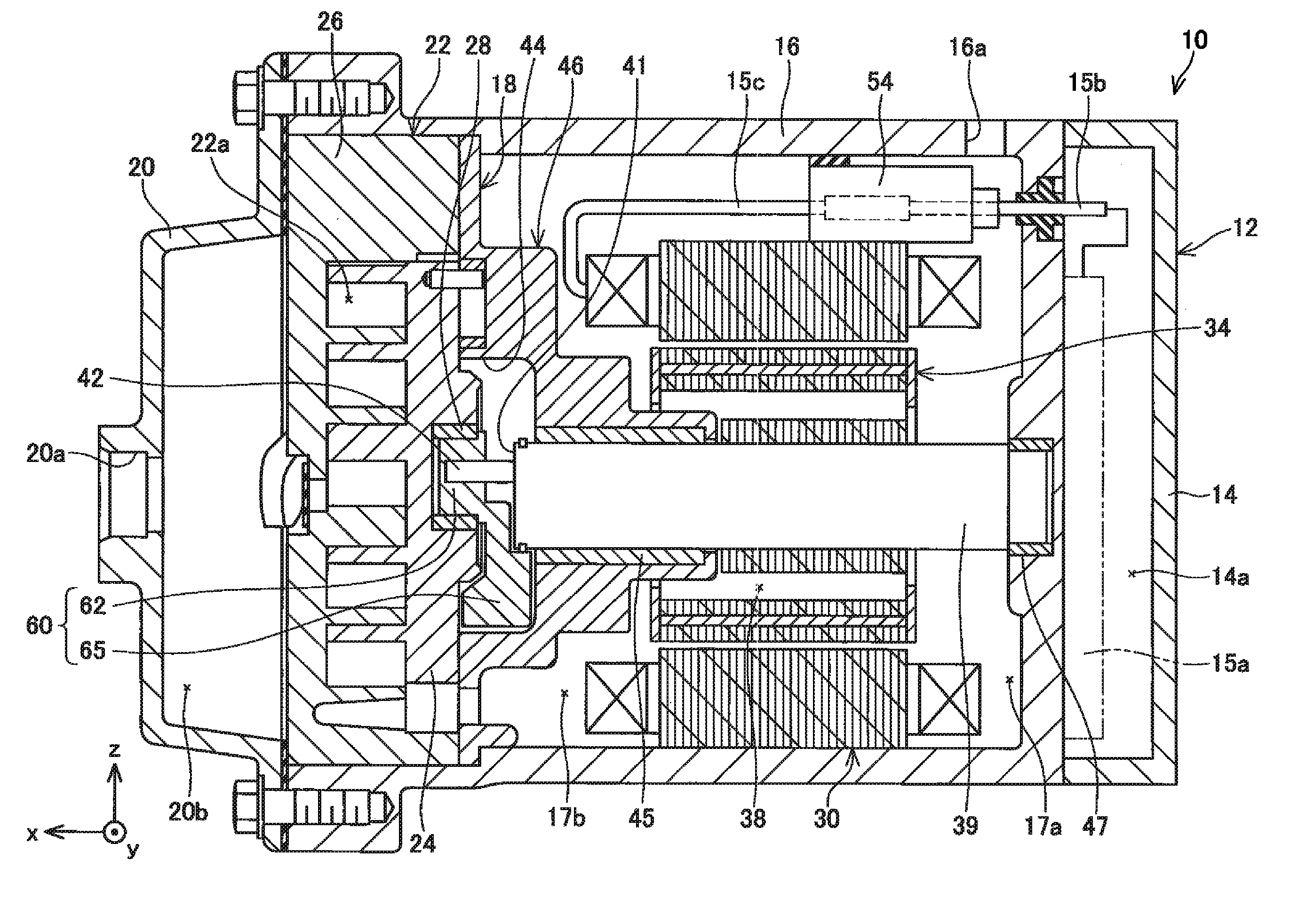
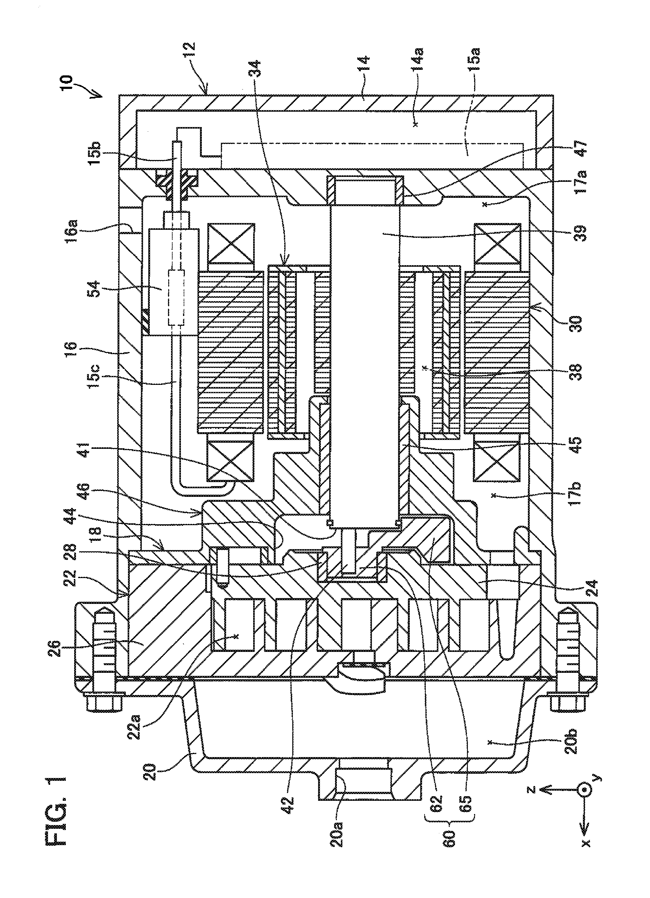
[0029]The overall configuration of the scroll compressor 10 according to a first embodiment is now explained with reference to FIG. 1. Note that, in the ensuing drawings, a part of the hatching is omitted in the cross sections. As shown in FIG. 1, the scroll compressor 10 comprises a housing 12, a cylindrical rotating shaft 39 rotatably supported by the housing 12, and electric motor (30, 34) and a compression unit 22 housed inside the housing 12. The electric motor (30, 34) is disposed on one end side (right end side of FIG. 1) of the rotating shaft 39, and the compression unit 22 is disposed on the other end side of the rotating shaft 39. In other words, the electric motor (30, 34) and the compression unit 22 are disposed along the axial direction of the rotating shaft 39. As described later, when the electric motor (30, 34) drives the rotating shaft 39, the compression unit 22 is driven by the rotating shaft 39.
[0030]The housing 12 comprises a bottomed cylindrical motor housing 1...
second modification example
[0053]A second modification example according to the first embodiment is now explained with reference to FIG. 6 and FIG. 7. In the ensuing explanation, only the points that differ from the first embodiment are explained, and the detailed explanation of configurations that are the same as the first embodiment is omitted.
[0054]With the scroll compressor according to the second modification example, a groove 70 is formed on the projecting portion 65a of the balancer-integrated bush 60 in substitute for the groove 43 being formed on the rotating shaft 39. The groove 70 is formed to make a full circle around the side face (that is, the face that is formed substantially vertical from the face 69) including the face 68 of the projecting portion 65a. A circular ring 100a is fitted onto the groove 70. As shown in FIG. 7, the diameter of the circular ring 100a is set to a thickness so that the circular ring 100a is not always in abutment with the peripheral surface of the rotating shaft 39 wh...
second embodiment
[0055]A second embodiment is now explained with reference to FIG. 8 and FIG. 9. In the ensuing explanation, only the points that differ from the first embodiment are explained, and the detailed explanation of configurations that are the same as the first embodiment is omitted.
[0056]With the scroll compressor according to the second embodiment, a rubber sheet 100b is disposed between the other end surface 41 of the rotating shaft 39 and the face 67 of the balancer 65 and between the peripheral surface of the rotating shaft 39 and the face 68 in substitute for attaching the O ring 100 to one end of the rotating shaft 39. The sheet 100b is configured from a sheet portion 100b1 spreading in the yz plane, and a sheet portion 100b2 extending from the sheet portion 100b1 in the −x direction. The sheet portion 100b1 has a substantially line-symmetric shape with regard to the axis B indicated with a dashed line. A hole having a diameter that is substantially the same as the diameter of the e...
PUM
 Abstract
Description
Claims
Application Information
 - R&D
- Intellectual Property
- Life Sciences
- Materials
- Tech Scout
- Unparalleled Data Quality
- Higher Quality Content
- 60% Fewer Hallucinations
Browse by: Latest US Patents, China's latest patents, Technical Efficacy Thesaurus, Application Domain, Technology Topic, Popular Technical Reports.
© 2025 PatSnap. All rights reserved.Legal|Privacy policy|Modern Slavery Act Transparency Statement|Sitemap|About US| Contact US: help@patsnap.com