Railway vehicle vibration damping device

Inactive Publication Date: 2014-09-11
KYB CORP
View PDF5 Cites 3 Cited by
  • Summary
  • Abstract
  • Description
  • Claims
  • Application Information

AI Technical Summary

Benefits of technology

The patent aims to make life more comfortable for railway passengers when they are in a curve section.

Problems solved by technology

Therefore, when the damping force is determined while the effect of the superimposed centrifugal acceleration remains on the sway direction velocity, the damping force becomes unnecessarily large, leading to a reduction in a passenger comfort of the railway vehicle.

Method used


Image

  • Railway vehicle vibration damping device
  • Railway vehicle vibration damping device
  • Railway vehicle vibration damping device

Examples


Embodiment Construction

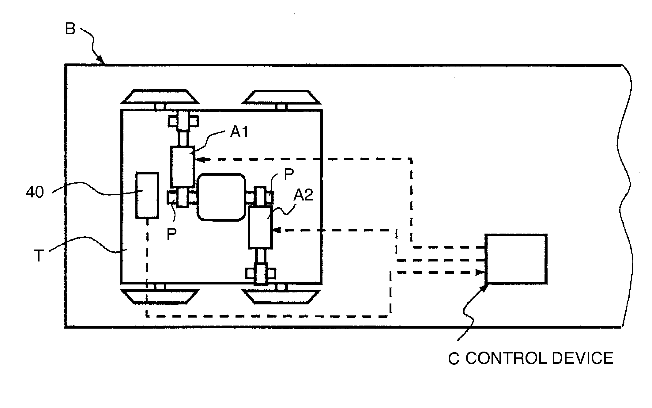
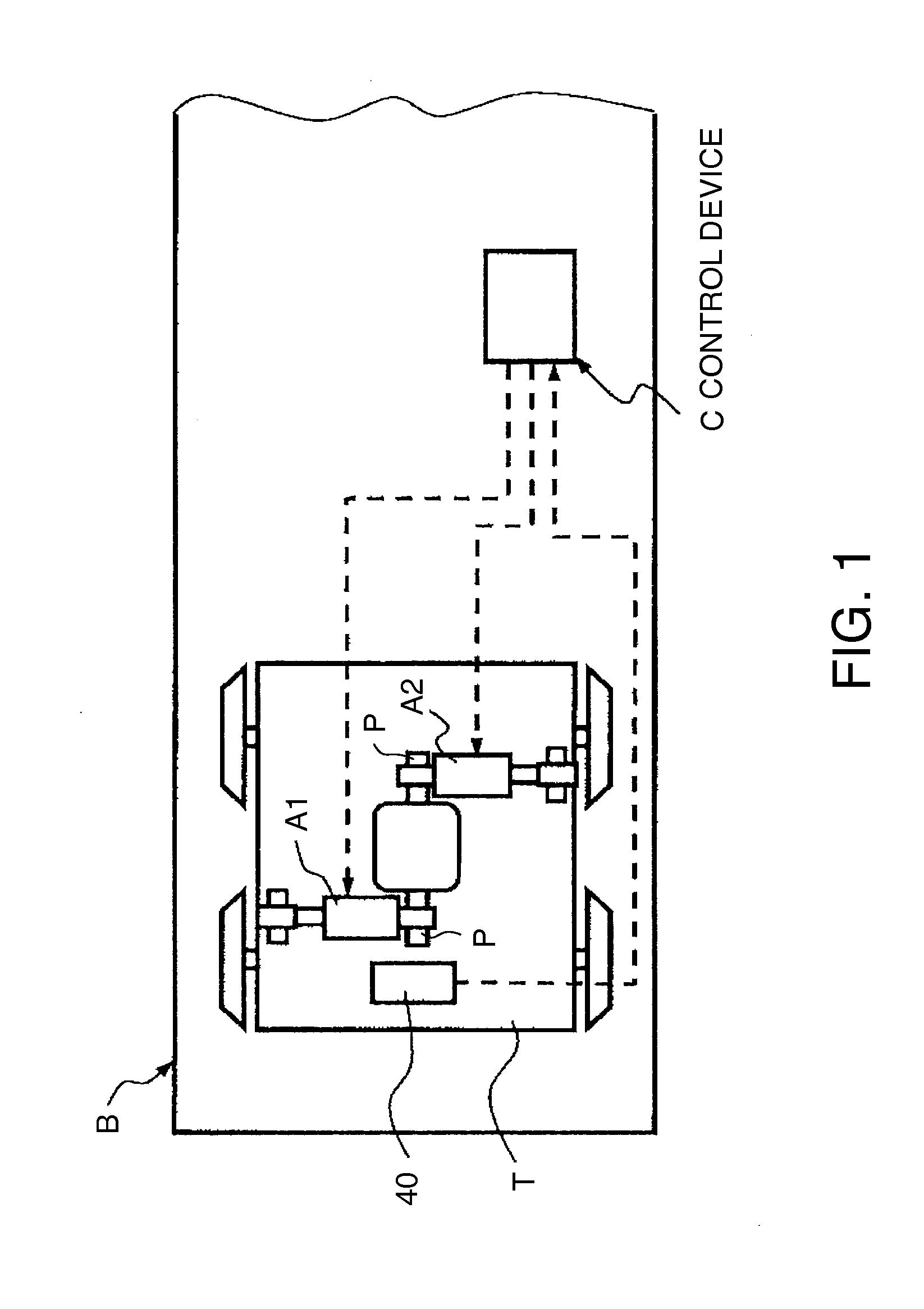
[0018]Referring to FIG. 1 of the drawings, a railway vehicle vibration damping device 1 according to an embodiment of this invention serves as a vibration damping device for a vehicle body B of a railway vehicle.

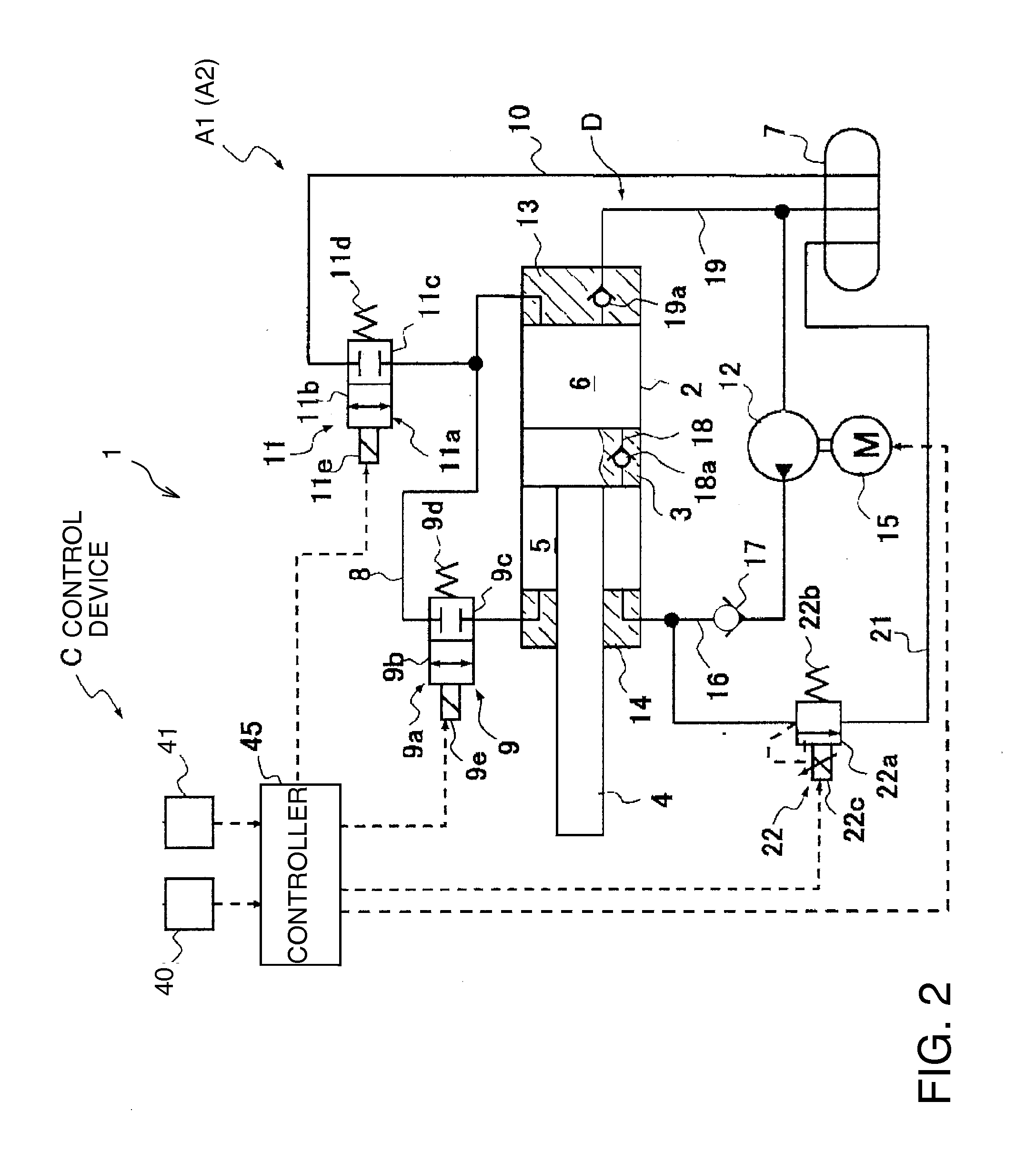
[0019]The railway vehicle vibration damping device 1 comprises hydraulic actuators A1 and A2 interposed between a bogie T and the vehicle body B of the railway vehicle, and a control device C that performs active control of the actuators A1 and A2. One end of each of the actuators A1 and A2 is coupled to a pin P projecting from the vehicle body B in a front-aft direction, and another end is coupled to the bogie T.

[0020]The control device C suppresses horizontal vibration of the vehicle body B in a vehicle transverse direction by performing active control of the actuators A1 and A2, or in other words by causing the actuators A1 and A2 to function as active dampers.

[0021]The control device C detects a horizontal acceleration α of the vehicle body B in the vehicle transverse di...


PUM


Abstract

A railway vehicle vibration damping device having at least two vibration suppression force generating sources interposed between a bogie and a vehicle body of a railway vehicle extracts from a transverse direction velocity of the vehicle body a frequency component at or above a frequency of a centrifugal acceleration of the vehicle body, and calculates a high frequency vibration suppression force on the basis thereof. When the railway vehicle travels in a curve section, at least a part of the vibration suppression force generating sources is caused to output the high frequency vibration suppression force, and the remaining vibration suppression force generating sources are caused to function as passive dampers. As a result, passenger comfort in the railway vehicle during travel in a curve section is improved.

Description

TECHNICAL FIELD[0001]This invention relates to suppression of vibration in a railway vehicle during travel on a curve.BACKGROUND ART[0002]A railway vehicle vibration damping device that suppresses vibration of a railway vehicle body in a right-left direction relative to a travel direction of the railway vehicle comprises, for example, a variable damping force damper interposed between the vehicle body and a bogie of the railway vehicle. A damping force required to suppress the vibration of the vehicle body is determined from a yaw direction angular velocity of the vehicle body and a sway direction velocity of the vehicle body in a vehicle body center, and a damping force of the variable damping force damper is adjusted so that the determined damping force can be generated.[0003]More specifically, a damping force required to suppress yaw direction vibration is calculated by multiplying a distance from the vehicle body center to a bogie center and a control gain by a yaw rate. Further...

Claims


Application Information

Patent Timeline
IPC IPC(8): B61F5/12B61F5/24
CPCB61F5/245B61F5/12F15B11/10F15B2211/20538F15B2211/3051F15B2211/3058F15B2211/50518F15B2211/513F15B2211/5159F16F9/46F16F15/002F16F2228/04F16F9/10B61F5/24
Inventor OGAWA, TAKAYUKI
Owner KYB CORP
Why Eureka
Try Eureka