Railway vehicle damping device

a technology for damping devices and railway vehicles, which is applied to railway components, bogies, transportation and packaging, etc., can solve the problems of insufficient damping force for suppressing vibration at the resonance frequency of the vehicle body, the difficulty of removing centrifugal acceleration, and the reduction of passenger comfort in the railway vehicle. , to achieve the effect of improving passenger comfort of the railway vehicle, reducing passenger comfort in the railway vehicle, and reducing the deterioration of the passenger comfort of the railway

Inactive Publication Date: 2016-05-17
KYB CORP
View PDF11 Cites 0 Cited by
  • Summary
  • Abstract
  • Description
  • Claims
  • Application Information

AI Technical Summary

Benefits of technology

[0007]With regard to the yaw rate, since the acceleration difference is obtained, the effect of the centrifugal acceleration acting on the vehicle body when the railway vehicle travels through a curve section can be eliminated. The sway direction velocity, on the other hand, is determined on the basis of a sum of the accelerations, and therefore the centrifugal acceleration is superimposed on the acceleration of the vibration. The effect of the centrifugal acceleration is not eliminated in the calculation of the sway direction velocity. When the railway vehicle increases in speed, the effect of the centrifugal acceleration is considerable, and therefore, when the damping force is determined in a state where the effect of the centrifugal acceleration remains superimposed on the sway direction velocity calculation, the damping force becomes excessively large, leading to a reduction in passenger comfort in the railway vehicle.
[0009]It is therefore an object of this invention to improve passenger comfort of a railway vehicle in a curve section.

Problems solved by technology

When the railway vehicle increases in speed, the effect of the centrifugal acceleration is considerable, and therefore, when the damping force is determined in a state where the effect of the centrifugal acceleration remains superimposed on the sway direction velocity calculation, the damping force becomes excessively large, leading to a reduction in passenger comfort in the railway vehicle.
It is however difficult to remove the centrifugal acceleration since, as described above, the frequency of the centrifugal acceleration and the resonance frequency are close.
In this case, however, the damping force for suppressing vibration at the resonance frequency of the vehicle body becomes insufficient, and therefore the passenger comfort of the railway vehicle again deteriorates.

Method used


Image

  • Railway vehicle damping device
  • Railway vehicle damping device
  • Railway vehicle damping device

Examples


Embodiment Construction

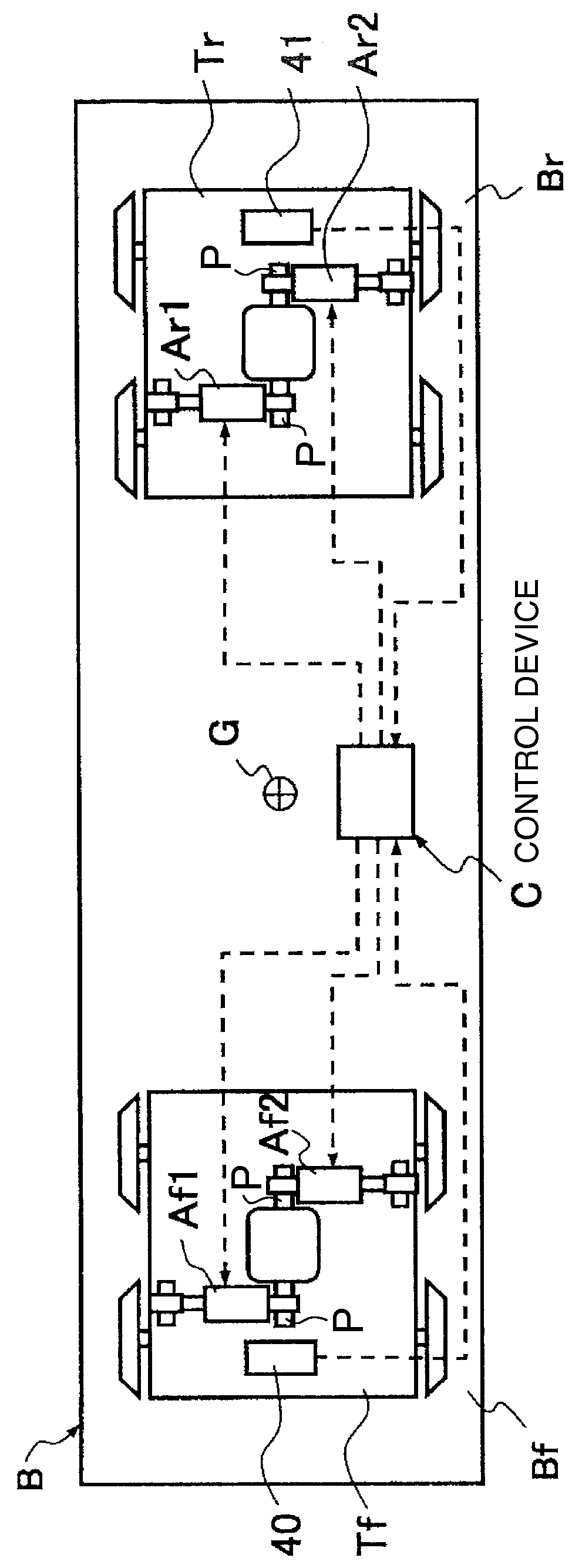
[0017]Referring to FIG. 1 of the drawings, a railway vehicle damping device 1 according to an embodiment of this invention is used as a damping device for a vehicle body B of a railway vehicle.

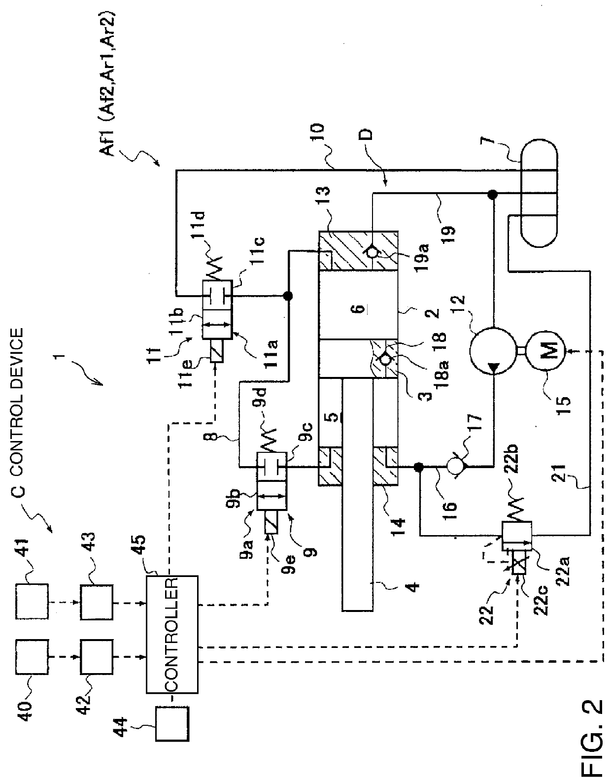
[0018]The railway vehicle damping device 1 comprises hydraulic actuators Af1, Af2 interposed between a front bogie Tf and the vehicle body B, hydraulic actuators Ar1, Ar2 interposed between a rear bogie Tr and the vehicle body B, and a control device C that controls the actuators Af1, Af2, Ar1, Ar2. More specifically, one end of each of the actuators Af1 and Af2 is coupled to a pin P projecting in a front-rear direction from a front portion Bf of the vehicle body B, and another end is coupled to the front bogie Tf. One end of each of the actuators Ar1 and Ar2 is coupled to another pin P projecting in the front-rear direction from a rear portion Br of the vehicle body B, and another end is coupled to the rear bogie Tr.

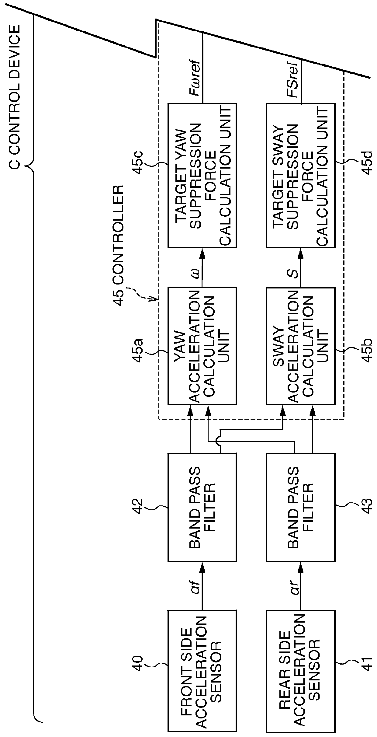
[0019]The control device C suppresses horizontal vibration of the vehicle bod...


PUM


Abstract

A railway vehicle damping device comprises at least two front side actuators interposed between a front bogie and a vehicle body of a railway vehicle, and at least two rear side actuators interposed between a rear bogie and the vehicle body of the railway vehicle, and suppresses vibration in a yaw direction of the vehicle body using a yaw suppression force generated by the actuators. After determining that the railway vehicle is traveling in a curve section, a control device causes at least one of the front side actuators and at least one of the rear side actuators to generate a yaw suppression force, and causes all of the remaining actuators to function as passive dampers. As a result, passenger comfort in the railway vehicle during travel in the curve section is improved.

Description

TECHNICAL FIELD[0001]This invention relates to suppression of vibration in a railway vehicle during travel on a curve.BACKGROUND ART[0002]A railway vehicle damping device that suppresses vibration of a railway vehicle body in a right-left direction relative to a running direction of the railway vehicle comprises, for example, a variable damping force damper interposed between the vehicle body and a bogie. A damping force required to suppress the vibration of the vehicle body is determined from a yaw direction angular velocity of the vehicle body and a sway direction velocity of the vehicle body in a vehicle body center, and a damping force of the variable damping force damper is adjusted so that the determined damping force can be generated.[0003]More specifically, a damping force required to suppress yaw direction vibration is calculated by multiplying a distance from a vehicle center to a bogie center and a control gain by a yaw rate. Further, a damping force required to suppress ...

Claims


Application Information

Patent Timeline
Patent Type & Authority Patents(United States)
IPC IPC(8): B61F5/22B61F5/24
CPCB61F5/245
Inventor OGAWA, TAKAYUKI
Owner KYB CORP
Why Eureka
Try Eureka