Active damping control for an electric vehicle or hybrid vehicle

Active Publication Date: 2014-09-11
ROBERT BOSCH GMBH
View PDF6 Cites 7 Cited by
  • Summary
  • Abstract
  • Description
  • Claims
  • Application Information

AI Technical Summary

Benefits of technology

[0016]Furthermore, in certain driving situations erroneous or corrupted sensor information can result in stimulation of oscillation of the vehicle drive train. In other words, e.g. inaccurate or incorrectly determined sensor information can lead to an effective worsening of the situation. Such erroneous drive train stimulation through inaccurate or erroneous sen

Problems solved by technology

Such occurring oscillations also mean, besides a loss of comfor

Method used


Image

  • Active damping control for an electric vehicle or hybrid vehicle
  • Active damping control for an electric vehicle or hybrid vehicle
  • Active damping control for an electric vehicle or hybrid vehicle

Examples


Example

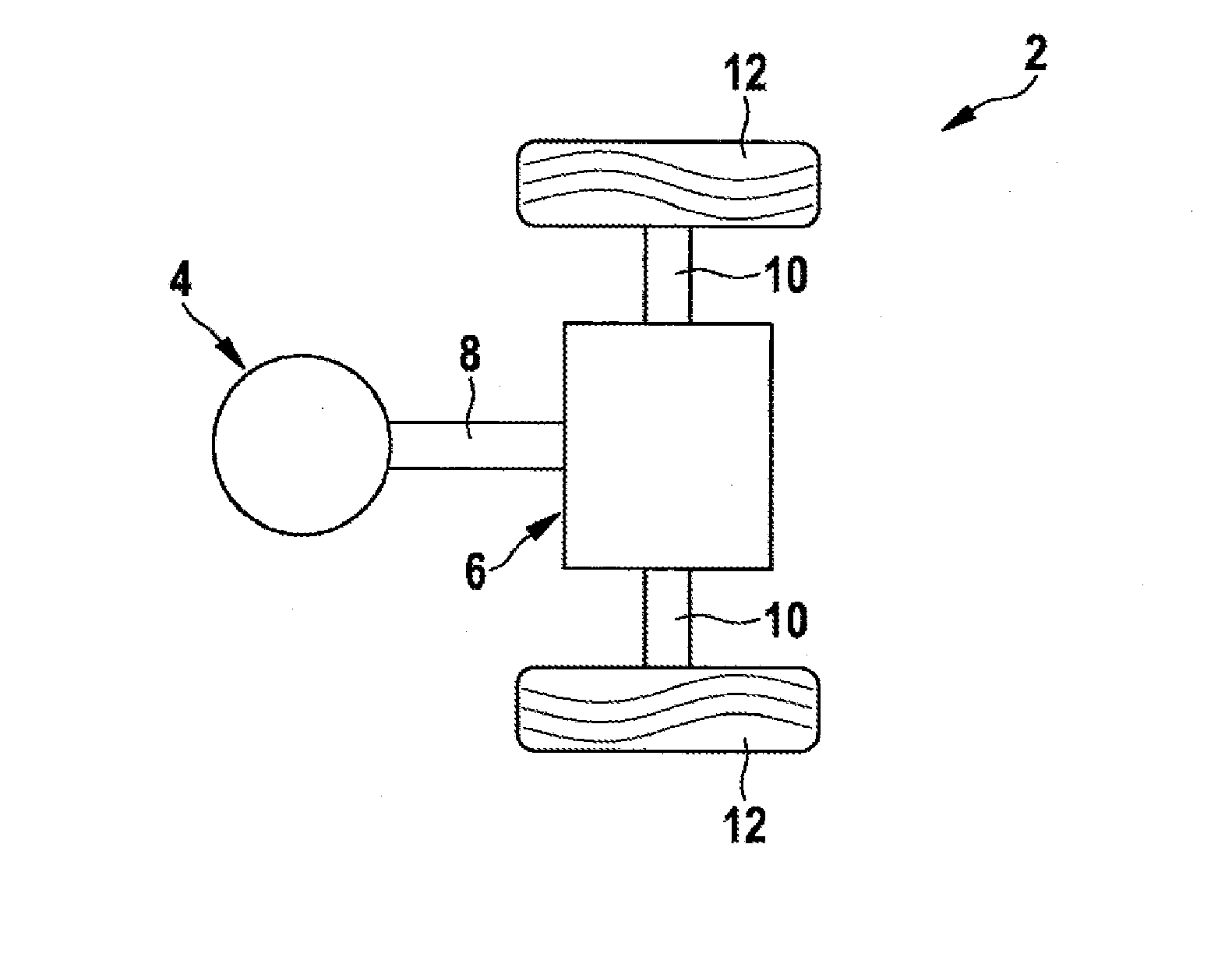
[0025]FIG. 2 shows a model of a vehicle drive train according to the present invention.

[0026]The modeled vehicle drive train 2 for a hybrid electric vehicle or an electric vehicle comprises an electric motor drive element 4, which is coupled to a gearbox 6 using a drive shaft 8. Starting from the gearbox 6, two drive wheels 12 are connected to the electric motor 4 via axle shafts 10 by way of example. A rotation of the electric motor 4 is thus transferred via the drive shaft 8, gearbox 6 and axle shafts 10 into a rotation of the drive wheels 12.

[0027]Because of the transfer of the rotary motion from the electric motor drive element 4 to the drive wheels 12 using a plurality of intermediate elements, especially by means of their predominant elasticities and dampings, electric motor 4 can vibrate when driving the drive wheels 12.

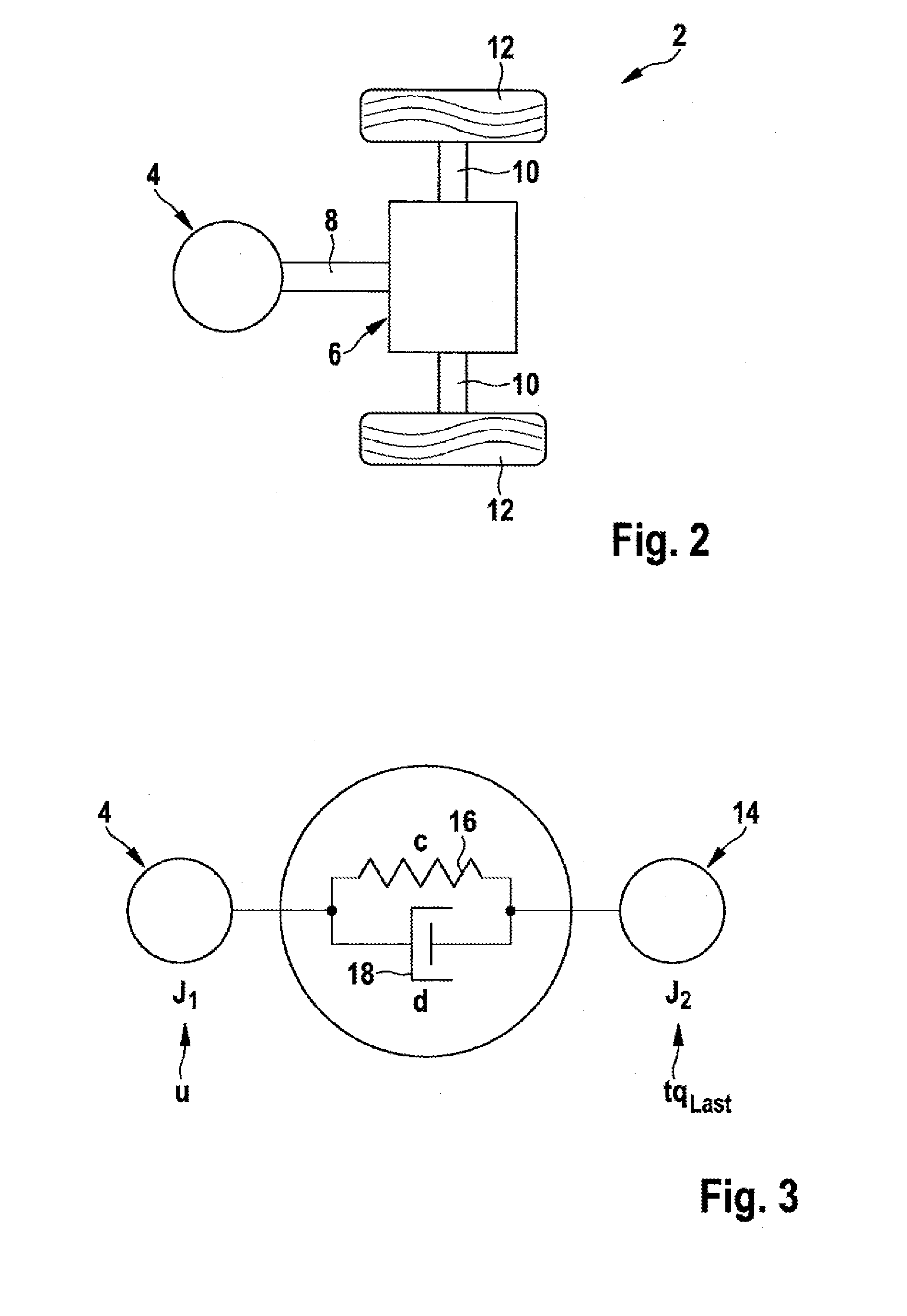
[0028]FIG. 3 shows an exemplary embodiment of a reduced drive train model rDTM according to the present invention, especially an equivalent circuit diagram or...


PUM


Abstract

The invention relates to a method (30) for the active damping control for an electric vehicle or hybrid vehicle having an electric motor drive element (4), comprising the steps of receiving a current target torque value (tqElmDes) of the electric motor drive element (4), determining a current rotational angle value (φElmAct) of the electric motor drive element (4), and determining a current damping torque value (tqDmp), characterized in that the current damping torque value (tqDmp) is determined using a reduced drive train model (rTSM).

Description

BACKGROUND OF THE INVENTION[0001]The present invention relates to drive technology in vehicles. In particular, the present invention relates to the damping of a vibration behavior of an electric motor drive element. The present invention also especially relates to a method for active damping control for an electric vehicle or hybrid vehicle having an electric motor drive element and a controller and a vehicle.[0002]Electric motors are being ever more often used as at least one drive component in motor vehicles. However, one property of a vehicle drive train having an electric motor as the drive motor is its ability to vibrate. It can therefore be possible that the revolution rate of an electric motor can oscillate significantly, especially during dynamic load changes, despite an essentially smooth profile of a propulsive torque of the electric motor.[0003]The illustrations of FIGS. 1a, b show the torque tqElm at the point in time t=1s as an essentially step increase from 0 Nm to e.g...

Claims


Application Information

Patent Timeline
IPC IPC(8): B60L15/20
CPCB60L15/20B60W30/20B60W2050/0041B60W2540/10B60W2710/083B60L2240/12B60L2240/421B60L2240/423B60L2240/461B60L2270/145Y02T10/64Y02T10/72
Inventor KLYMENKO, MYKHAYLOMECKS, MICHAELKRETSCHMER, MARKUSGOETTING, GUNTHER
Owner ROBERT BOSCH GMBH
Why Eureka
Try Eureka