Check patentability & draft patents in minutes with Patsnap Eureka AI!
Endotracheal Tube Holding Device with Bite Block
Inactive Publication Date: 2014-09-18
HOLLISTER INCORPORAED
View PDF18 Cites 25 Cited by
Summary
Abstract
Description
Claims
Application Information
AI Technical Summary
This helps you quickly interpret patents by identifying the three key elements:
Problems solved by technology
Method used
Benefits of technology
Benefits of technology
The patent describes a device called a bite block that has an insertion slot for inserting an endotracheal tube. There is also a living hinge or relief near the insertion slot that makes the device flexible enough to allow the tube to be inserted from the side. This makes it easier to intubate a patient without causing any damage to their mouth or tongue.
Problems solved by technology
However, the '504 patent does not include the cheek pads and cheek plates.
One problem with these and other known ET tube holding devices is that the patient may sometimes bite down hard or clamp onto the ET tube with their teeth or gums (denture wearers).
This can restrict or close off the airway within the tube.
These known products are generally large, cumbersome, and complicated devices that can be difficult to manipulate and install.
Another problem with these types of ET tube holding devices is that the tube often is accompanied by one or more accessory lines that also pass into the patient.
Method used
Image
Click on the blue label to locate the original text in one second.
Reading with bidirectional positioning of images and text.
Examples
Embodiment Construction
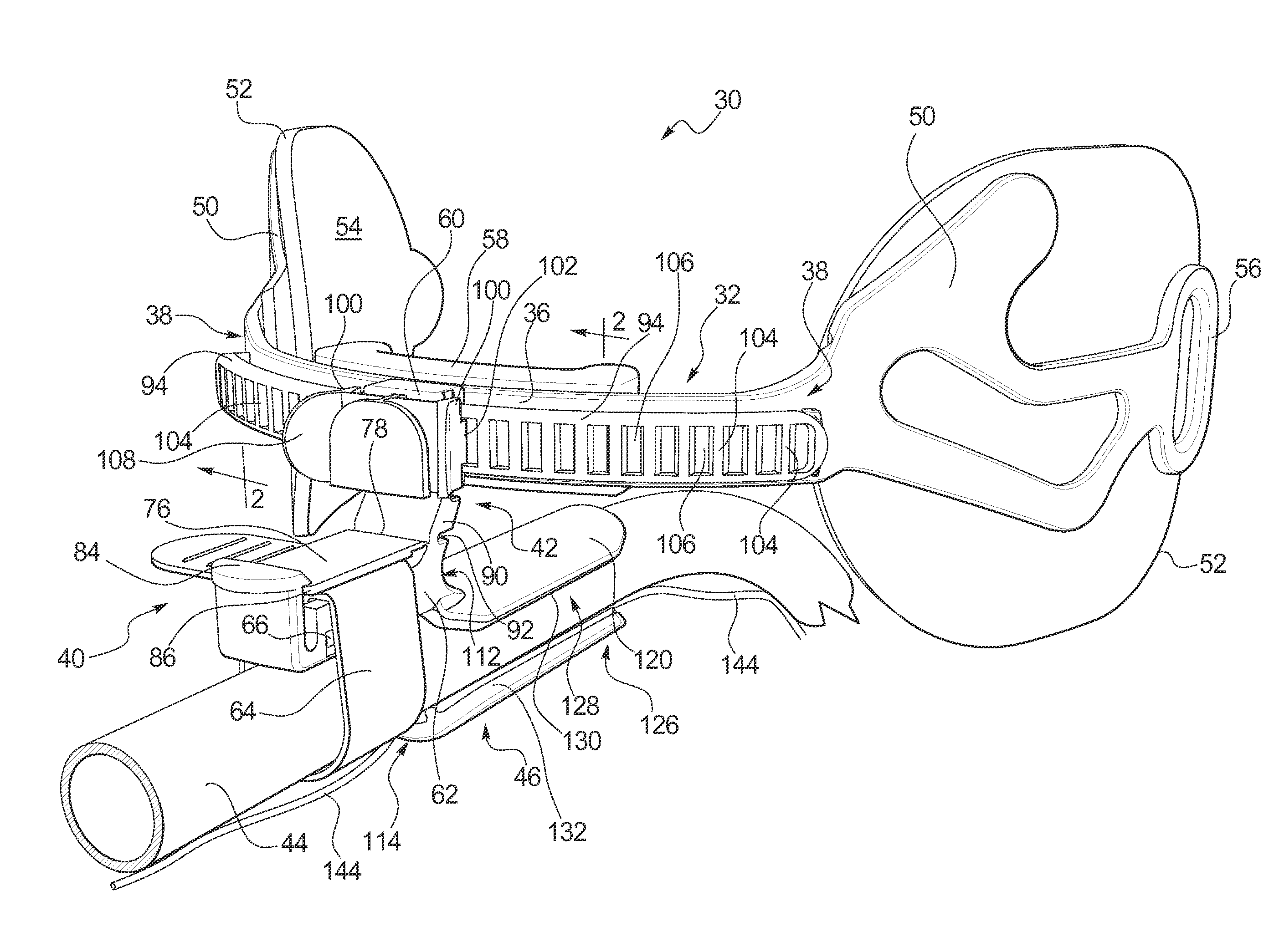
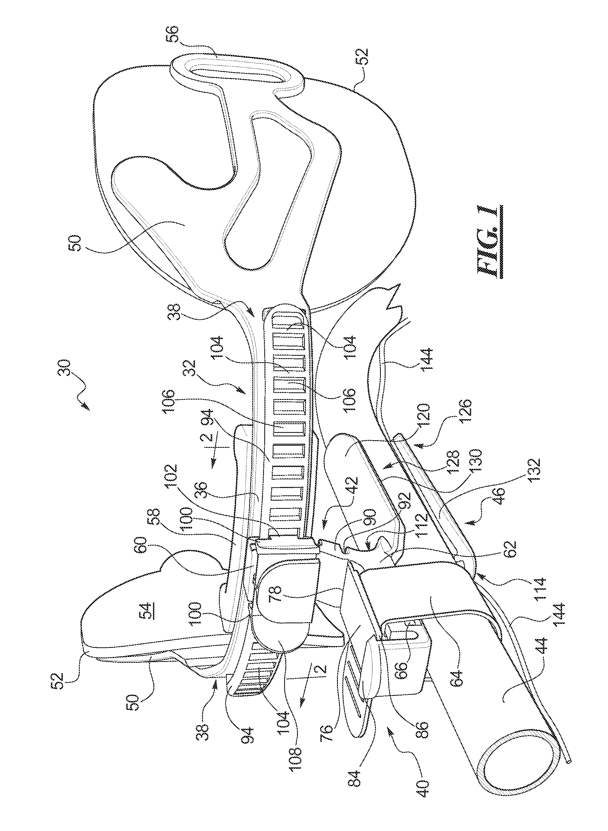
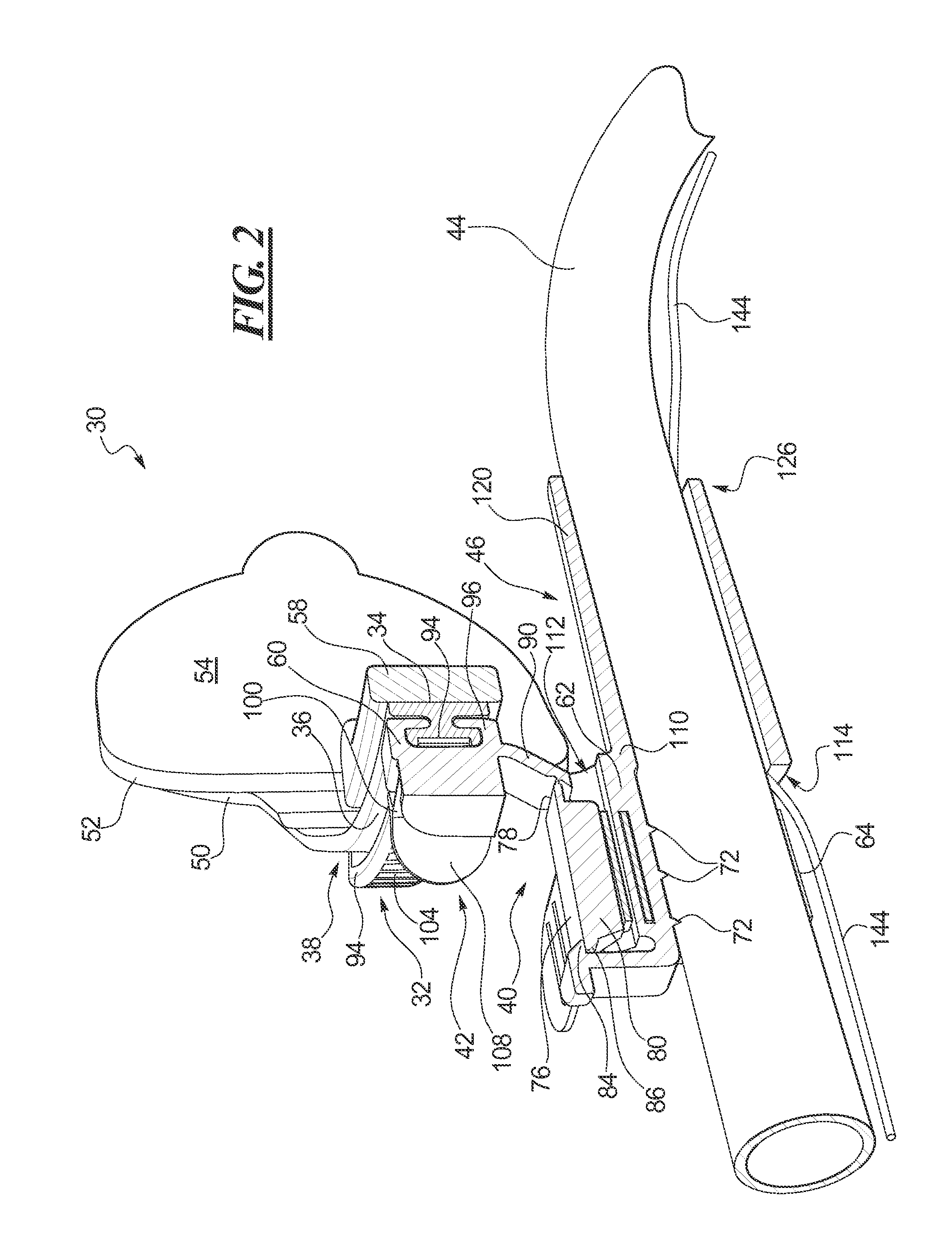
[0071]The disclosed ET tube holding devices solve or improve upon one or more of the above-noted and / or other problems and disadvantages with prior know holding devices. In one example, the disclosed devices have a bite block integrated into a tube holder portion of the device. In one example, the disclosed devices have a tube holder that is side-to-side adjustable along with an ET tube secured by the device. In one example, the disclosed devices have a bite block that is integrally molded as a part of the tube holder. In one example, the disclosed devices have a bite block with one or more features to assist in inserting an ET tube, retaining the ET tube in position once inserted, and accommodating an accessory line that passes within the bite block but outside of the ET tube. These and other objects, features, and advantages of the present invention will become apparent to those having ordinary skill in the art upon reading this disclosure.
[0072]Turning now to the drawings, FIGS. ...
PUM
Abstract
A device for holding an endotracheal tube has a slide track configured to fit adjacent a lip on a patient's face. The track has a face contacting side, an exposed side, and a pair of opposite ends. A tube holder is coupled to and slidable along the track. A positioning mechanism is releasably lockable to allow selective lateral repositioning of the tube holder and an endotracheal tube held thereby along the track and to retain the tube holder at a selected position along the track without removing the device from the patient or an endotracheal tube from the device. A bite block is carried by the tube holder and slidable therewith along the track. The bite block has a tubular wall with a central opening along a length of the bite block and a pair of opposite open ends. The bite block is positioned spaced vertically from the track and has a portion extending rearward beyond the face contacting side of the track.
Description
BACKGROUND[0001]1. Field of the Disclosure[0002]The present invention is generally directed to medical tube devices, and more particularly to a device for holding an endotracheal tube on a patient and having a bite block integrated with the device.[0003]2. Description of Related Art[0004]Endotracheal (ET) tubes are commonly inserted through the mouth and into the trachea of patients under critical care. The ET tube is used to maintain an open airway for the patient to breathe and to allow mechanical assistance of breathing. ET tubes are often placed prior to surgery or are used on trauma or critically ill patients that may require intubation for extended periods of time. Many instances in which a patient is intubated require that the tube remain in place for approximately 48 to 72 hours and, in some circumstances, the period of use may be extended for 7 to 14 days or more[0005]There are many known methods and devices for securing an ET tube on a patient. One such device is manufactu...
Claims
Application Information
Patent Timeline
Application Date:The date an application was filed.
Publication Date:The date a patent or application was officially published.
First Publication Date:The earliest publication date of a patent with the same application number.
Issue Date:Publication date of the patent grant document.
PCT Entry Date:The Entry date of PCT National Phase.
Estimated Expiry Date:The statutory expiry date of a patent right according to the Patent Law, and it is the longest term of protection that the patent right can achieve without the termination of the patent right due to other reasons(Term extension factor has been taken into account ).
Invalid Date:Actual expiry date is based on effective date or publication date of legal transaction data of invalid patent.
Inventor VISCONTI, PETER L.LEADINGHAM, BRIAN T.TETZLAFF, PATRICK C.WISNER, PAOLA M.HANTKE, RICHARD J.SHANAHAN PHEIL, MEAGAN R.KNAUZ, DAVID A.BERGER, CHERYL D.CISKO, GEORGE J.DANG, THAI H.GILMAN, THOMAS H.MEADE, NOAH K.CHUNG, TZE WAN PANSYAUGUSTYN, CHRISTINAMARCH, DANIEL A.MCDONOUGH, DAVID
