
Pneumatic system for operating row treating units for multi-row agriculture implements

a technology of pneumatic system and agricultural implement, which is applied in the field of pneumatic system for operating row treating unit for multi-row agricultural implement, operation of implement, can solve the problems of seed trenching, difficulty in adjusting the unit to accommodate, and seed spacing and depth problems, and achieve the effect of convenient starting

Active Publication Date: 2014-09-18
L & B MFG +1
View PDF2 Cites 1 Cited by
  • Summary
  • Abstract
  • Description
  • Claims
  • Application Information

AI Technical Summary

Benefits of technology

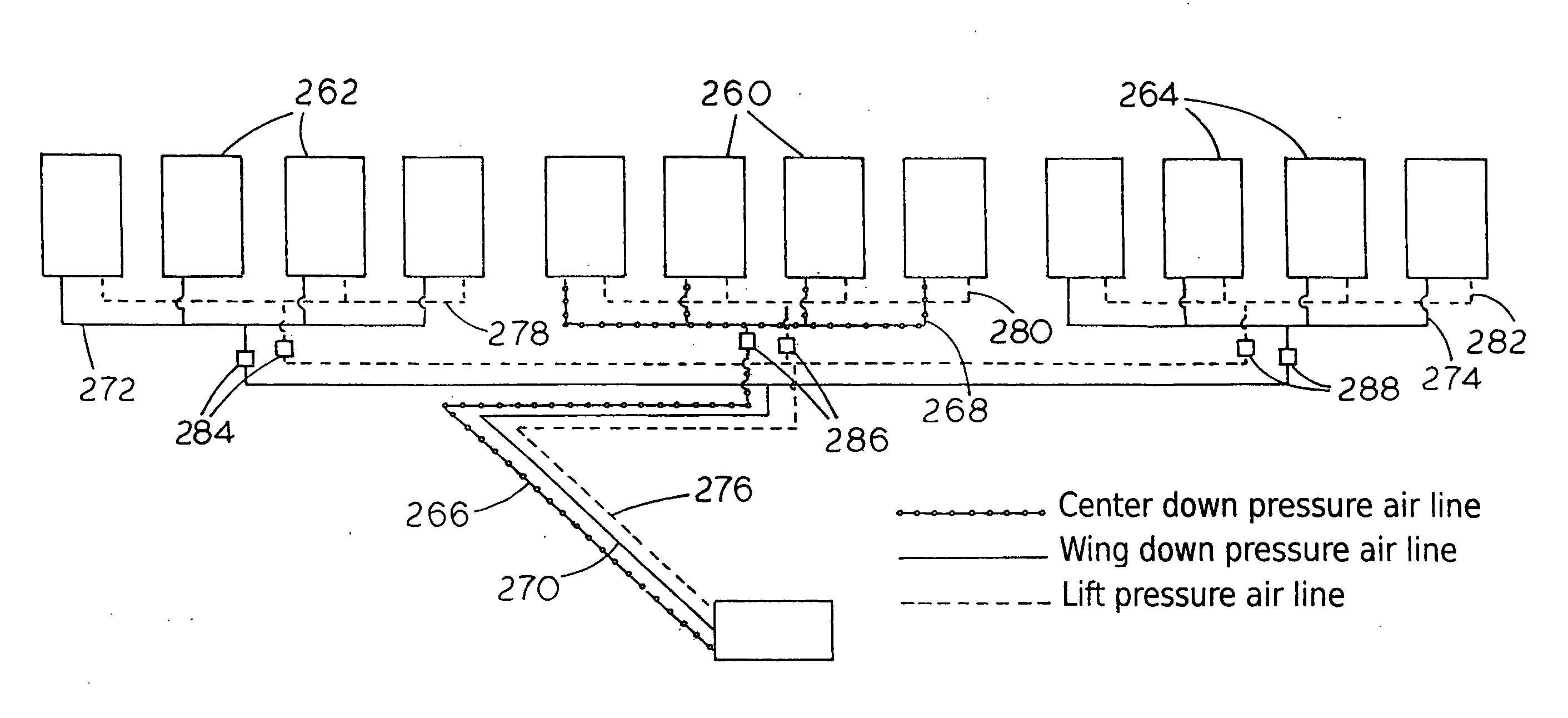
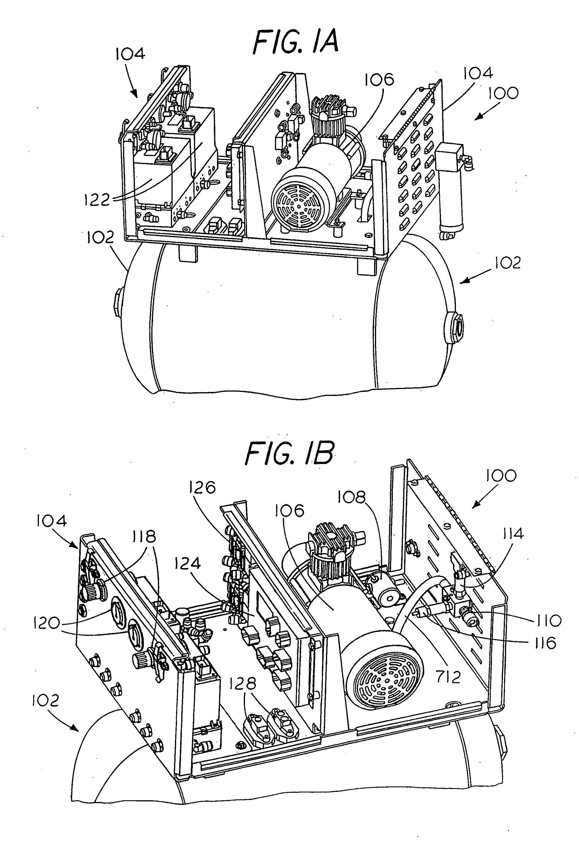
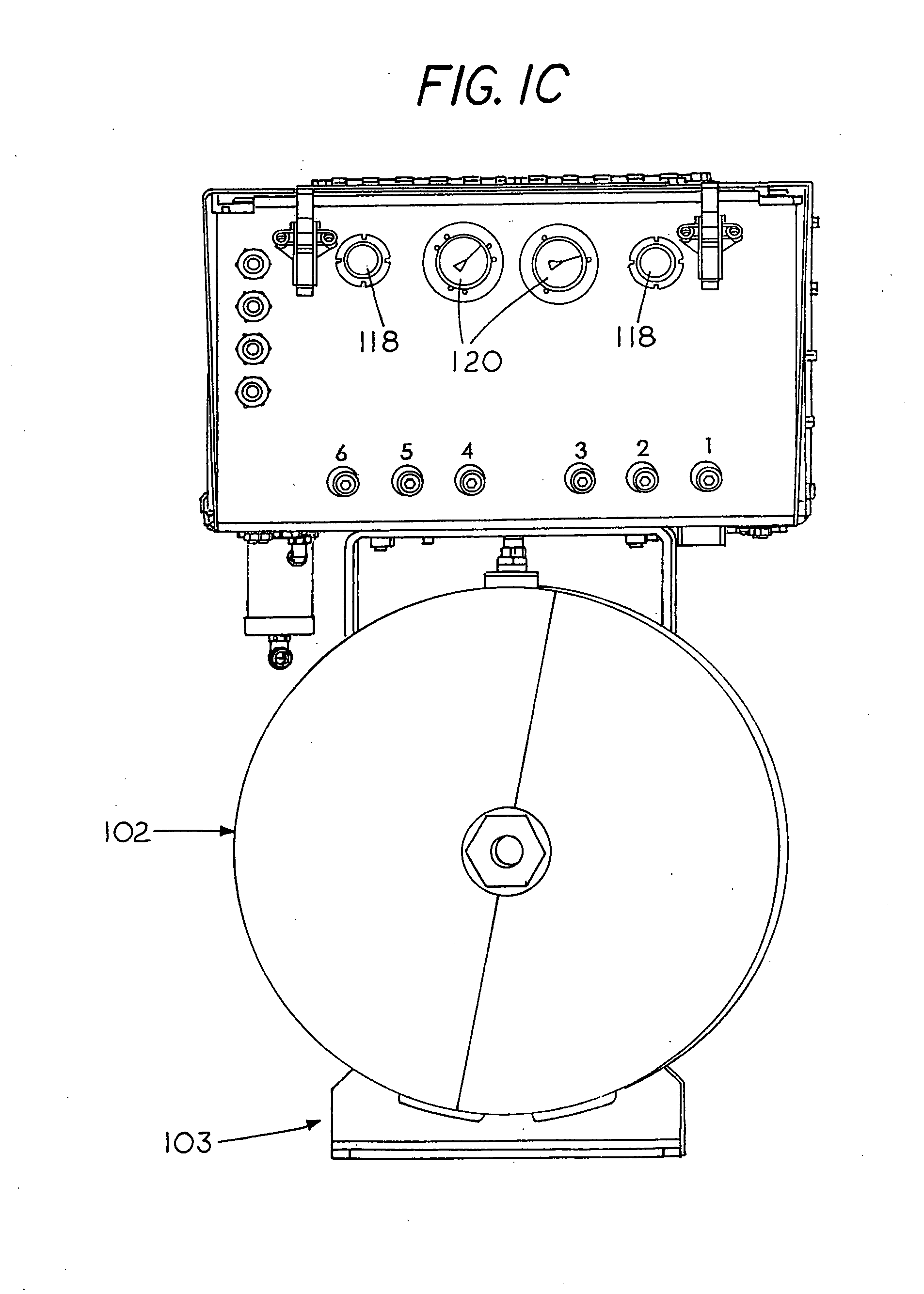
The system described in this patent includes an accumulator tank, air compressor, adjustable air regulators, air lines and dump valves, as well as a remote switch panel located in the cab of a pulling tractor. The accumulator needs to be large enough to perform various functions with extra capacity. The control box containing the compressor and valving is located on the accumulator tank. The tank also has a programmable solenoid dump valve to drain moisture from the bottom of the tank. The air compressor is capable of producing 150 psi continuous duty. It includes an electronic solenoid and pressure switch to control the pressure on the accumulator tank, as well as a solenoid valve head dump for easier starting. Overall, this system allows for efficient and effective air usage in industrial applications.

Problems solved by technology

With regard to all of these implements, it has been difficult to adjust them to accommodate variations in soil types and conditions prior to and during the planting operation.
A problem with prior closing wheel assemblies is that in some instances downward directed force will cause the closing wheels to penetrate to a depth that interferes with the seeds planted at the bottom of the trench and causes problems with the seed spacing and depth.
This may even lead to some seeds being thrown from the seed trench.
Thus too little pressure results in voids or air pockets in the soil, and too much pressure will compact the soil to tightly making it difficult for the plants to sprout through the hard packed soil and moisture will not penetrate the ground as easily as desired.

Method used


Image

  • Pneumatic system for operating row treating units for multi-row agriculture implements
  • Pneumatic system for operating row treating units for multi-row agriculture implements
  • Pneumatic system for operating row treating units for multi-row agriculture implements

Examples


Embodiment Construction

[0028]The detailed description of the illustrative embodiments is intended to illustrate representative examples of the inventive concepts and is not intended to exhaust or limit the scope of those concepts. The examples are to be read in connection with the accompanying drawings, which are to be considered part of the entire written description of this invention. In the description, relative terms such as “lower”, “upper”, “horizontal”, “vertical”, “above”, “below”, “up”, “down”, “top” and “bottom”, “left” and “right” as well as derivatives thereof (e.g., “horizontally”, “downwardly”, “upwardly”, etc.) should be construed to refer to the orientation as then described or as shown in the drawings under discussion. These relative terms are for convenience of description and do not require that the apparatus be constructed or operated in a particular orientation. Terms such as “connected”, “connecting”, “attached”, “attaching”, “join” and “joining” are used interchangeably and refer to...


PUM


Abstract

A pneumatic system capable of operating a number of pneumatic operators associated with a plurality of row units attached to a multi-row planting or seeding system or other tow bar arrangement, or the like, and with an ability to modulate or control the adjustment of air pressures, manually and electronically, raise and lower implements and adjust the force exerted by individual implements on the soil associated with each row unit is disclosed. The system can be controlled remotely as from a remote switch or control panel located in the cab of an associated tractor.

Description

CROSS-REFERENCED TO RELATED APPLICATIONS[0001]Not applicableSTATEMENT REGARDING FEDERALLY SPONSORED RESEARCH OR DEVELOPMENT[0002]Not applicableBACKGROUND OF THE INVENTION[0003]I. Field of the Invention[0004]This invention is directed generally to the field of agricultural machinery, and more particularly, it relates to the operation of implements generally associated with the planting function, including preplanting tillage implements and said trench closing and packing implements generally used in combination with multi-row planting or seeding devices, fertilizer applicators and other soil treating systems. Specifically, the invention relates to a pneumatic implement deployment and control system designed to supply and control air to a variety of pneumatically operated tillage and fertilizing implements including rolling basket, row cleaning or trash whipping devices, coulter devices and / or seed trench closing and packing wheels of planter row units. The rolling basket, trash whip,...

Claims


Application Information

Patent Timeline
Patent Type & Authority Applications(United States)
IPC IPC(8): A01B63/32
CPCA01B63/32A01C5/06A01B63/008
Inventor VAN BUSKIRK, LOYD C.VAN BUSKIRK, DYLAN C.ALLENSWORTH, DEREK K.
Owner L & B MFG
Learn More