Vehicle Brake System With Dual Acting Plunger Assembly
a technology of plunger assembly and brake system, which is applied in the direction of brake system, brake components, transportation and packaging, etc., can solve the problems of increased stopping distance, increased slippage between the wheel and the road surface, and possible loss of directional control
- Summary
- Abstract
- Description
- Claims
- Application Information
AI Technical Summary
Benefits of technology
Problems solved by technology
Method used
Image
Examples
first embodiment
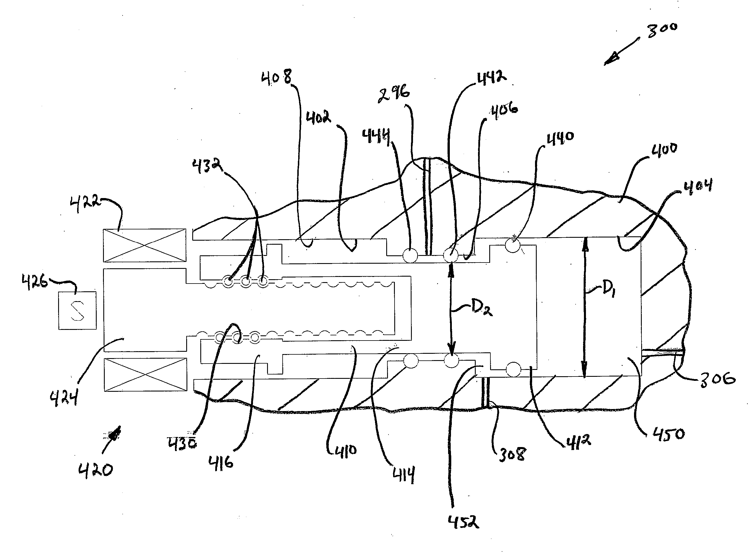
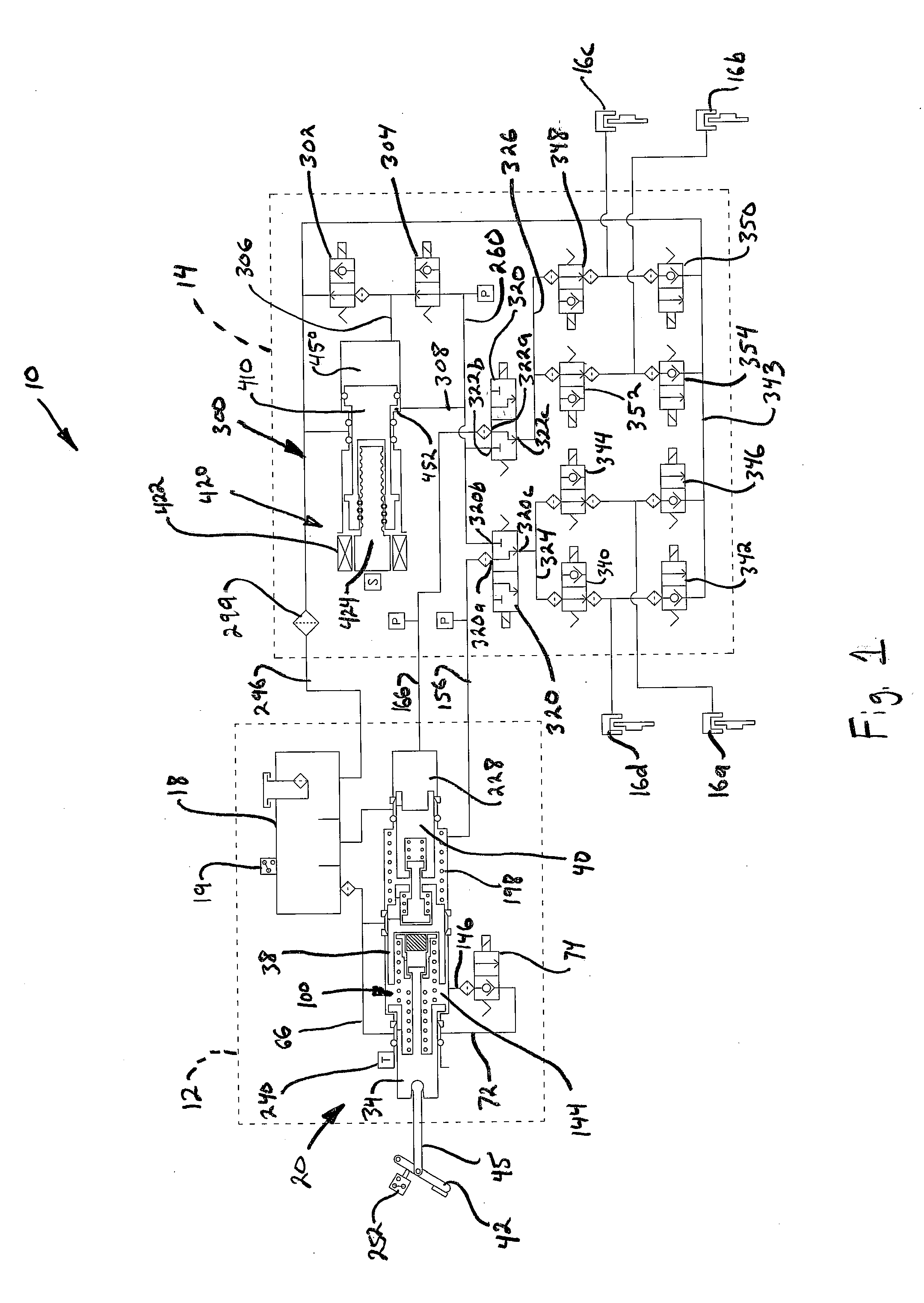
[0021]Referring now to the drawings, there is schematically illustrated in FIG. 1 a vehicle brake system, indicated generally at 10. The brake system 10 is a hydraulic boost braking system in which boosted fluid pressure is utilized to apply braking forces for the brake system 10. The brake system 10 may suitably be used on a ground vehicle such as an automotive vehicle having four wheels with a wheel brake associated with each wheel. Furthermore, the brake system 10 can be provided with other braking functions such as anti-lock braking (ABS) and other slip control features to effectively brake the vehicle, as will be discussed below.
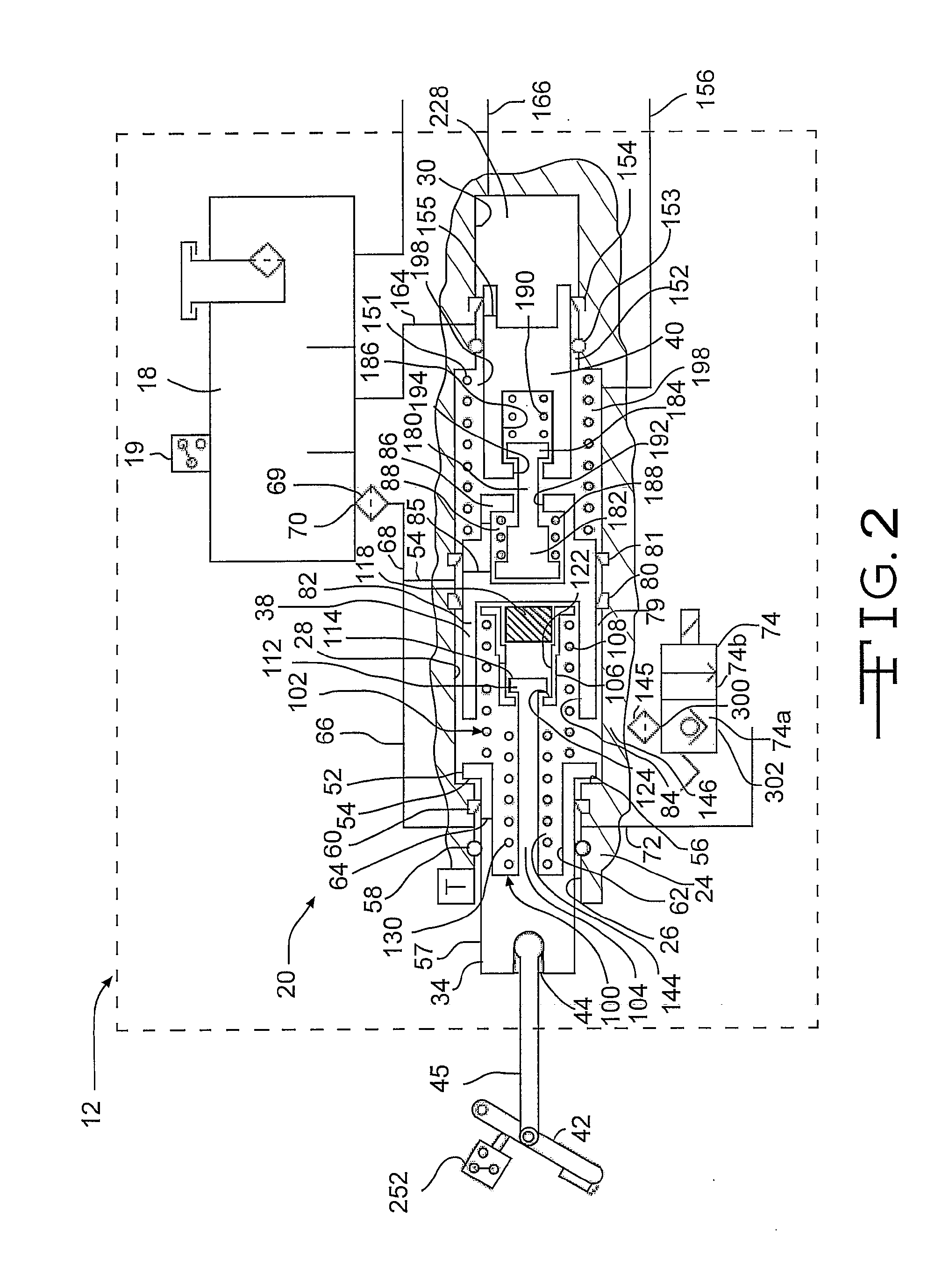
[0022]The brake system 10 generally includes a first block or brake pedal unit assembly, indicated by broken lines 12, and a second block or hydraulic control unit, indicated by broken lines 14. The various components of the brake system 10 are housed in the brake pedal unit assembly 12 and the hydraulic control unit 14. The brake pedal unit assembly 12...
second embodiment
[0069]There is illustrated in FIG. 5 a schematic illustration of a brake system, indicated generally at 600. The brake system 600 is similar to the brake system 10 of FIG. 1 and, therefore, like functions and structures will not be described. Similar to the brake system 10, the brake system 600 includes a brake pedal unit 612, a hydraulic control unit 614, and wheel brakes 616a-d.
[0070]The brake system 600 does not include a venting valve like the venting valve 302 of the system 10. Instead, the brake system 600 includes a plunger assembly 620 similar to the plunger assembly 300. One of the differences is that the plunger assembly 620 has a piston 622 with a check valve 624 mounted therein. The check valve 624 permits fluid to flow from a first pressure chamber 630 to a reservoir conduit 632 (in communication with a reservoir 613) via a conduit 634 within the piston 622. It is noted that the check valve 624 prevents the flow of fluid from the reservoir 613 to the first pressure cha...
third embodiment
[0081]There is illustrated in FIG. 7 a schematic illustration of a brake system, indicated generally at 800. The brake system 800 is similar to the brake system 600 and, therefore, like functions and structures will not be described. The brake system 10 is ideally suited for large passenger vehicles or trucks. Generally, larger vehicles require more braking power and more fluid volume than brake systems for smaller vehicles. This generally requires a larger consumption of power for the motor for the plunger assembly.
[0082]The brake system 800 includes a brake pedal unit 812, a hydraulic control unit 814, and wheel brakes 816a-d. The brake assembly 800 further includes a plunger assembly 820 having a piston 822 with a check valve 824 mounted therein. The check valve 824 permits fluid to flow from a first pressure chamber 830 to a reservoir conduit 832 (in communication with a reservoir 813) via a conduit 834 within the piston 822. The check valve 824 prevents the flow of fluid from t...
PUM
 Abstract
Description
Claims
Application Information
 - R&D
- Intellectual Property
- Life Sciences
- Materials
- Tech Scout
- Unparalleled Data Quality
- Higher Quality Content
- 60% Fewer Hallucinations
Browse by: Latest US Patents, China's latest patents, Technical Efficacy Thesaurus, Application Domain, Technology Topic, Popular Technical Reports.
© 2025 PatSnap. All rights reserved.Legal|Privacy policy|Modern Slavery Act Transparency Statement|Sitemap|About US| Contact US: help@patsnap.com


