
Indentation hardness test system having an autolearning shading corrector

a test system and shading corrector technology, applied in the field of test systems, can solve problems such as stealing valuable time from operators

Inactive Publication Date: 2014-09-18
LECO CORPORATION
View PDF40 Cites 18 Cited by
  • Summary
  • Abstract
  • Description
  • Claims
  • Application Information

AI Technical Summary

Benefits of technology

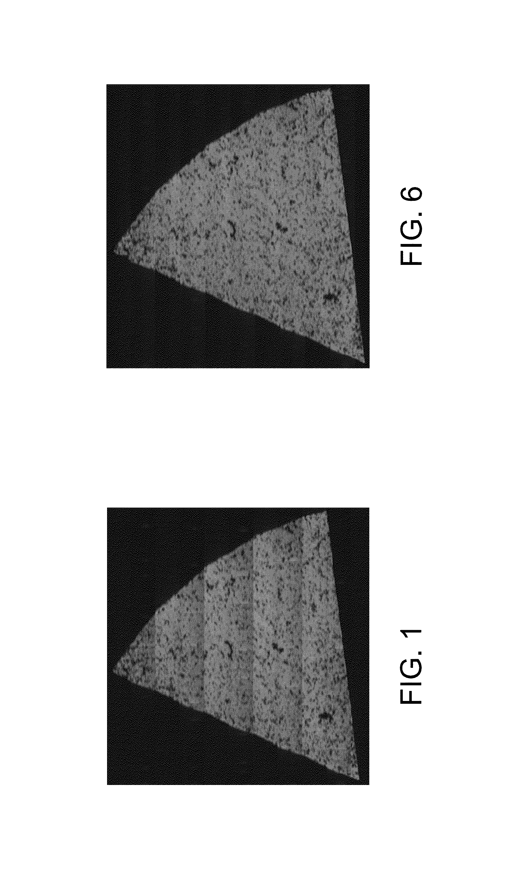
The present invention provides an indentation hardness test system for testing the hardness of a test object. The system includes a frame with an attached indenter, a movable stage for receiving a part, a camera for capturing images of the part, a display, a processor, and a memory subsystem. The system uses a series of magnified image frames to capture different parts of the part and calculates the average pixel intensity of each frame. A correction factor is then determined for each pixel based on the average pixel intensity and the raw pixel data. The system then performs shading correction on the raw pixel data by adjusting the raw pixel value based on the correction factor. A composite image of the part is generated by assembling the series of image frames with the shading correction. The technical effect of this invention is to provide a more accurate and reliable method for testing the hardness of a part by measuring its hardness through a series of image frames with shading correction.

Problems solved by technology

Other sources of shading include imperfections, distortions and contaminants in the optical path.
This approach requires periodic manual operation for each objective lens, which takes valuable time from the operator.

Method used


Image

  • Indentation hardness test system having an autolearning shading corrector
  • Indentation hardness test system having an autolearning shading corrector
  • Indentation hardness test system having an autolearning shading corrector

Examples


Embodiment Construction

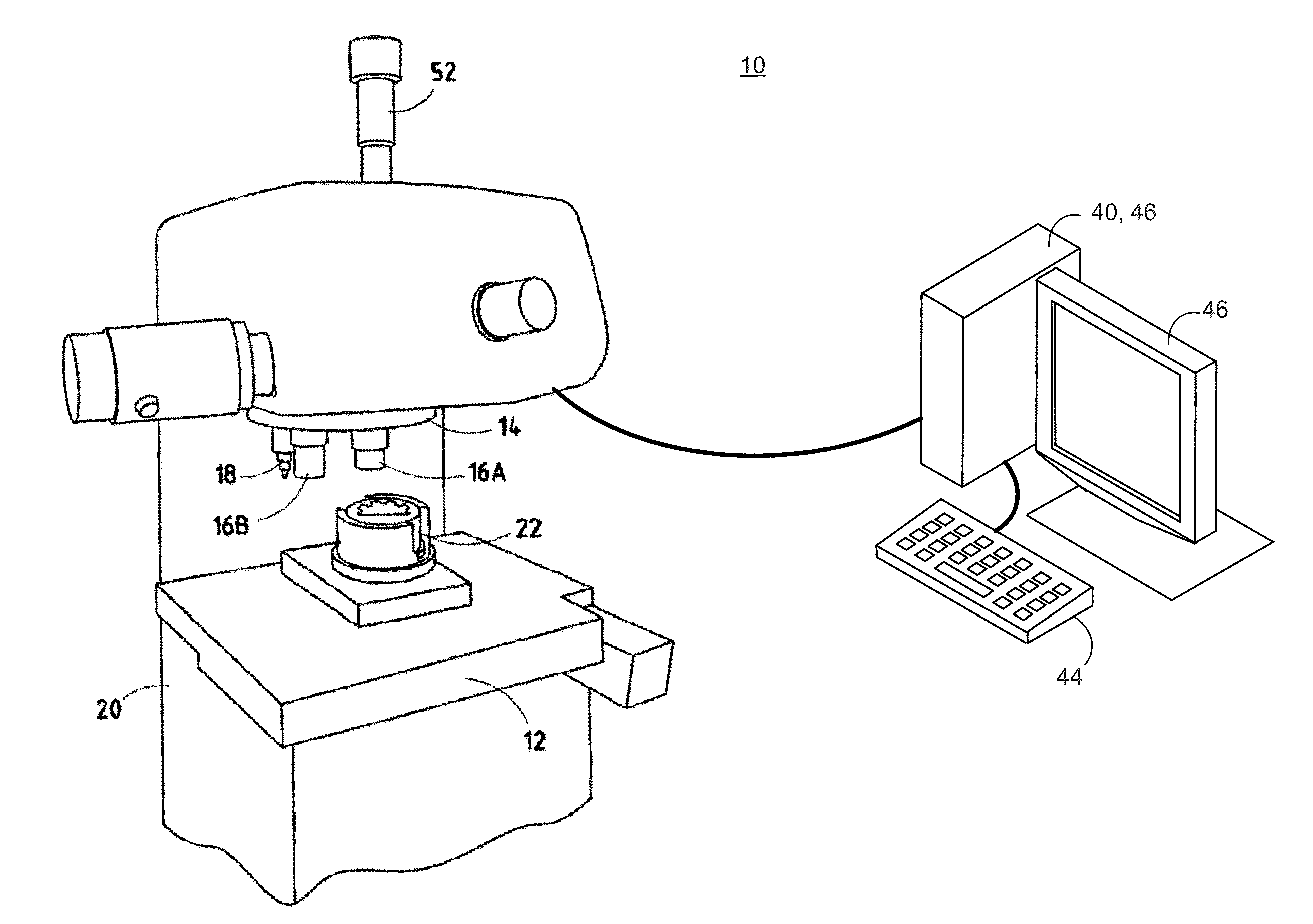
[0017]Reference will now be made in detail to the present preferred embodiments, examples of which are illustrated in the accompanying drawings. Wherever possible, the same reference numerals will be used throughout the drawings to refer to the same or like parts. In the drawings, the depicted structural elements are not to scale and certain components are enlarged relative to the other components for purposes of emphasis and understanding.

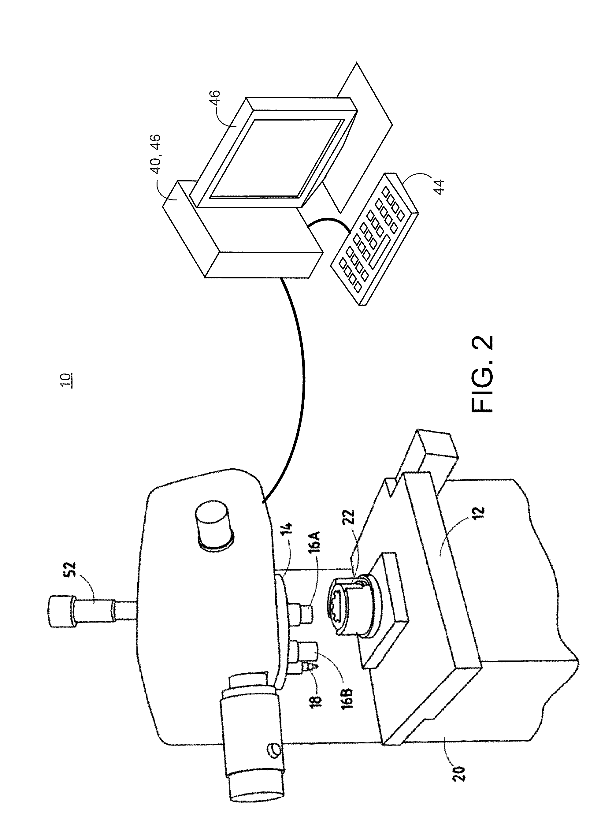
[0018]The embodiments described herein relate to an indentation hardness test system and a method for performing shading correction. An exemplary indentation hardness test system is first described with reference to FIGS. 2 and 3 followed by a description with reference to FIGS. 4 and 5 of a method of shading correction that may be performed by the indentation hardness test system.

[0019]A system according to the various embodiments described herein can be implemented using an indentation hardness test system that includes: a light microscope, a di...


PUM


Abstract

An indentation hardness test system is provided that includes: a frame including an attached indenter; a movable stage for receiving a part attached to the frame; a camera; a display; a processor; and a memory subsystem. The processor performs the steps of: (a) capturing images of different portions of the part; (b) for each image, computing an average intensity; (c) computing an average intensity across all images; (d) for each pixel, computing PixelAverageDeltan(x,y) as a function of the raw pixel data and the average pixel intensity of the image frame; (e) for each pixel, computing a correction factor using the average intensity across all images and PixelAverageDeltan(x,y); (f) performing shading correction by adjusting the raw pixel values by corresponding correction factors; and (g) generating a composite image of the part. Steps (b)-(e) may be performed on moving images while not including stationary images in the computations of those steps.

Description

BACKGROUND OF THE INVENTION[0001]The present invention is generally directed to a test system and, more specifically, to an indentation hardness test system and to an auto-learning shading corrector.[0002]Hardness testing has been found to be useful for material evaluation and quality control of manufacturing processes and research and development endeavors. The hardness of an object, although empirical in nature, can be correlated to tensile strength for many metals and provides an indicator of wear-resistance and ductility of a material. A typical indentation hardness tester utilizes a calibrated machine to force a diamond indenter (of a desired geometry) into the surface of a material being evaluated. The indentation dimension (dimensions) is (are) then measured with a light microscope after load removal. A determination of the hardness of the material under test may then be obtained by dividing the force applied to the indenter by the projected area of the permanent impression m...

Claims


Application Information

Patent Timeline
IPC IPC(8): G06K9/36G06V10/20
CPCG06K9/36G06T2207/10056G06T2207/30136G06V10/20G06T5/94
Inventor HAUCK, JOHN M.BARRINGHAM, JR., JAMES W.
Owner LECO CORPORATION
Learn More