Fluid delivery system and method for treatment

a technology of fluid delivery system and fluid, applied in the field of fluid delivery system and treatment, can solve the problems of difficulty in maintaining a desired temperature (or temperature range), difficulty in maintaining a desired temperature, and conventional liquid coolant supply system failure to provide a sufficiently compact and efficient closed loop system, etc., to achieve the effect of effective and efficient heat transfer, improve heat transfer, and limited desirable heat transfer of fluids

Active Publication Date: 2014-09-18
NUVAIRA INC
View PDF7 Cites 66 Cited by
  • Summary
  • Abstract
  • Description
  • Claims
  • Application Information

AI Technical Summary

Benefits of technology

[0021]In one aspect, the fluid cooling supply system may include at least one biasing mechanism to provide sufficient and given biasing force between the cartridge and the cooling device. The biasing mechanism can be at least one magnet arranged to removably couple the cartridge to the cooling device. The at least one magnet may be magnetically coupleable to at least one corresponding magnet adjacent the thermal plate of the cooling device, or it may be magnetically coupleable to a magnetically attractive element of the cooling device. The at least one biasing mechanism may include two pairs of magnets positioned on opposing ends of the cartridge and each coupleable to corresponding pairs of magnets adjacent the thermal plate. The corresponding pairs of magnets may be secured to a biasing frame coupled to the thermal plate of the cooling device. The biasing frame may extend around a perimeter of the thermal plate. The corresponding pairs of magnets of the biasing frame are aligned with and attractable to the pairs of magnets of the cartridge to bias the cartridge to the thermal plate with a given biasing force. The result of utilizing a naturally-occurring means and mechanism is that most or all of the surface area of the thermally conductive surface of the cartridge is biased against the most or all of the surface area of the thermal plate of the cooling device at a given biasing force to effectively and efficiently transfer heat from the fluid during cooling of the fluid.
[0022]In several aspects of the present disclosure the cooling system includes features that act to bias the cartridge to the cooling device with a sufficient and given force to effectuate and improve heat transfer from the fluid. Notably, available TECs are limited by the amount of heat flux that is able to be dissipated by the TEC; thus, desirable heat transfer of the fluid is somewhat limited in some applications. Also, TECs are known to be somewhat inefficient as compared to other cooling devices, so it is important to reduce efficiencies of the system in other aspects, such as the design of the cartridge and configuration of other components in the system, like the position of the pump. Furthermore, a sufficient biasing force between the thermally conductive surface of the cartridge and the thermal plate of the cooling device is important because of the nature of the material of the surfaces biased to each other. The thermally conductive surface may be copper and thermal plates are typically a ceramic substrate. Under a microscope, even the smoothest of cooper and ceramic surfaces show countless ridges and valleys that may affect thermal conductivity between the two materials if a sufficient biasing force is not applied and maintained during heat transfer. According, the present disclosure provides an effective means and various mechanisms to adequately bias the cartridge to the cooling device to increase surface-to-surface contact between the biased surfaces to efficiently chill the fluid during treatment of a patient. Such improved surface contact ultimately reduces heat losses in the system so that a constant and controllable fluid temperature is supplied to a treatment device in a patient. This is of particular importance when operating the cooling system during pulmonary treatment, which requires, at certain intervals, a constant fluid temperature and a constant fluid pressure for a particular duration during a treatment session.
[0023]In one aspect, the cartridge may be formed and provided in a pre-stressed configuration to improve heat transfer and reduce heat losses. Accordingly, the cartridge may be manufactured to be in a first state (pre-stressed) when disengaged from the cooling device, and in a second state when engaged to the cooling device. The first state is achieved by forming the cartridge to have a profile with a convex shape relative to the thermal plate of the cooling device such that a lateral arc of the cartridge extends from a left side to a right side of the cartridge. Accordingly, when the cartridge is engaged to the thermal plate (i.e., by utilizing the pairs of magnets on left and right sides of the cartridge, for example), by virtue of the convex shape and the force of the magnets, the thermally conductive surface of the cartridge will have a profile that is a substantially flat shape relative to the thermal plate because the magnets on the sides of the cartridge will tend to “flatten out” the profile of the cartridge. This pre-stressed configuration tends to prevent a slight “buckling” that may be experience by the cartridge such that the result would be a concave cartridge that is not completely or adequately biased to the cooling machine. Thus, the pre-stressed configuration of the cartridge provides greater surface-to-surface contact between the thermally conductive sur...

Problems solved by technology

It has been recognized that delivering a liquid coolant to a treatment site in a patient during treatment can present several difficulties to practitioners.
For example, it can be challenging to maintain a desired temperature (or range of temperatures) at a treatment site within a patient for a desired interval during a treatment session.
This is partially due to heat losses that may exist from the time when the fluid is chilled to the time when the fluid is supplied to a patient for treating the tissue.
It has been recognized that conventional liquid coolant supply systems fail to provide a sufficiently compact and efficient closed loop system that allows for control of the temperatur...

Method used


Image

  • Fluid delivery system and method for treatment
  • Fluid delivery system and method for treatment
  • Fluid delivery system and method for treatment

Examples


Embodiment Construction

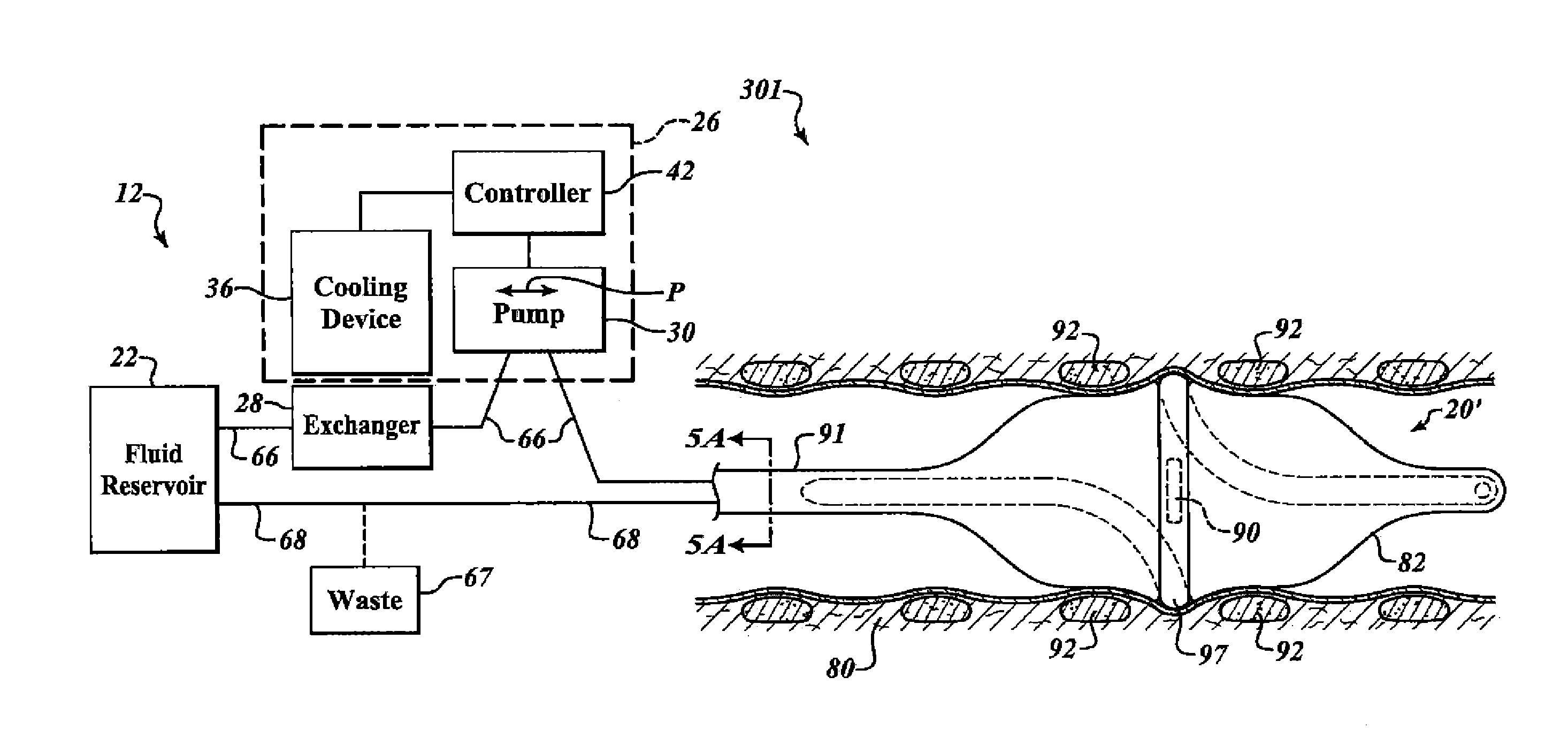
[0059]According to the present disclosure, FIGS. 1-7B illustrate a first aspect of a treatment system having a fluid cooling supply system for treatment of a patient, and FIGS. 8-13C illustrate a second aspect of a treatment system having a fluid cooling supply system for treatment of a patient. It will be understood that various configurations described with reference to the first and second aspects may be combined into further configurations and aspects, which may be further discussed in the present disclosure regarding particular configurations.

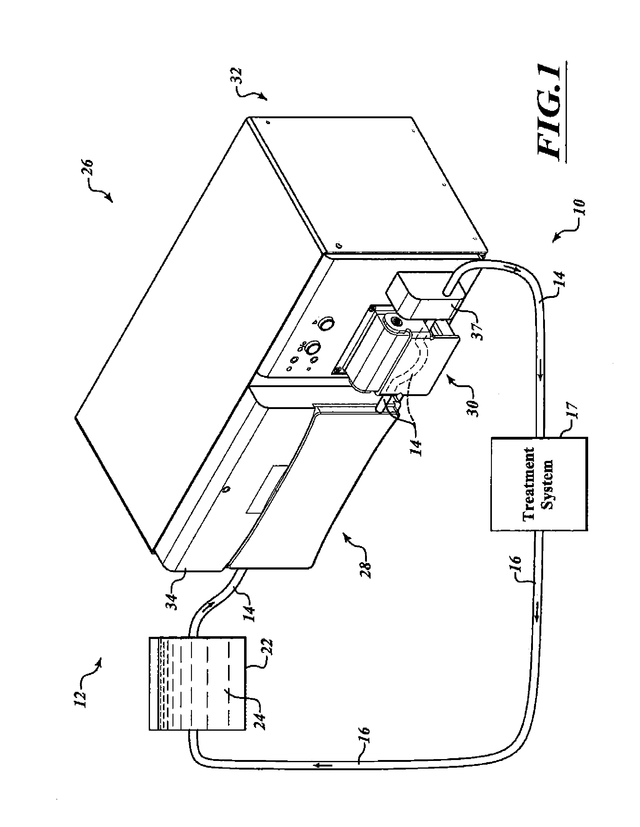
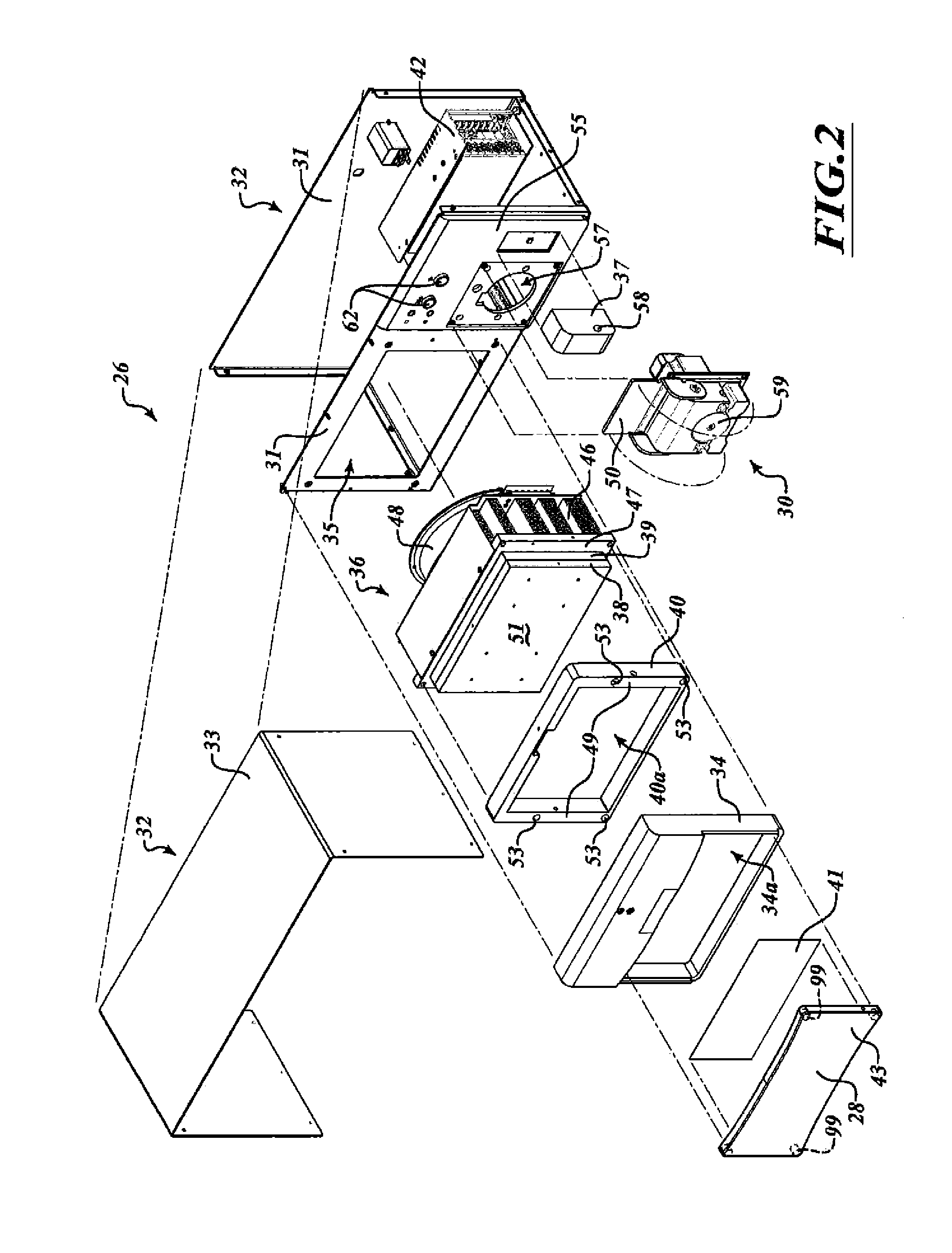
[0060]FIGS. 1 and 2 illustrate a system 10 that includes a fluid cooling supply system 12 coupled to a treatment system 17. FIG. 2 shows a partially exploded view of certain components of the fluid cooling supply system 12 of FIG. 1.

[0061]In the example in FIG. 1, the fluid cooling supply system 12 is coupled to the treatment system 17. The treatment system 17 may be positionable at least partially in a patient (FIG. 4). The fluid cooling ...


PUM


Abstract

A treatment system includes a fluid cooling supply system for chilling and delivering liquid coolant to a patient. The fluid cooling supply system includes a cooling device and a heat exchanger device. The heat exchanger device is biased to the cooling device and is in fluid communication with a treatment device in a patient. The fluid cooling supply system includes at least one biasing mechanism to provide a given biasing force between the heat exchanger device and the cooling device to effectuate and improve heat transfer. The liquid coolant may be circulated through an energy delivery device positioned in an airway of a patient to preserve tissue. The system is controlled to circulate liquid coolant at a given temperature and pressure for a selected amount of time during pulmonary treatment of a patient.

Description

RELATED APPLICATION[0001]The present application claims the benefit of U.S. Provisional Application No. 61 / 779,371 filed Mar. 13, 2013, which is incorporated herein in its entirety by reference.BACKGROUND[0002]1. Technical Field[0003]The present invention generally relates to systems and associated methods for delivering a cooled fluid during treatment of a patient.[0004]2. Description of the Related Art[0005]Several conventional medical treatments include supplying a cooled liquid directly to the human body. For example, a cooled liquid may be supplied to the blood stream to cool an organ, such as the brain, to protect the organ from injury.[0006]Other conventional medical treatments include supplying a cooled liquid to a device used to treat the human body. For example, several particularly effective treatments for pulmonary disorders are described in, for example, U.S. Pat. No. 8,088,127, titled, “Systems, Assemblies, and Methods for Treating a Bronchial Tree,” and U.S. Patent Ap...

Claims


Application Information

Patent Timeline
IPC IPC(8): A61B18/14A61M25/10
CPCA61B18/1492A61B2018/00541A61B2018/00434A61B2018/00023A61B18/14A61B2018/00029A61B2018/00035A61B2018/00577
Inventor KAVECKIS, RYANHARSHMAN, EDWARD S.MAYSE, MARTIN L.STREETER, JOHN
Owner NUVAIRA INC
Why Eureka
Try Eureka