
Integrated Circuit with a Patching Function

Active Publication Date: 2014-09-18
DIALOG SEMICONDUCTOR
View PDF5 Cites 7 Cited by
  • Summary
  • Abstract
  • Description
  • Claims
  • Application Information

AI Technical Summary

Benefits of technology

[0020]The integrated circuit may comprise a communication unit for receiving an external signal representing a patch of the data stored on the OTP. The control unit may be arranged for storing subsequently received patches onto

Problems solved by technology

A disadvantage of the OTP is that if a certain memory space is programmed, it cannot be programmed again.
Thus, if a bug in the firmware exists, the system cannot be upgraded since the OTP cannot be “corrected”.
Ano

Method used


Image

  • Integrated Circuit with a Patching Function
  • Integrated Circuit with a Patching Function
  • Integrated Circuit with a Patching Function

Examples


Example

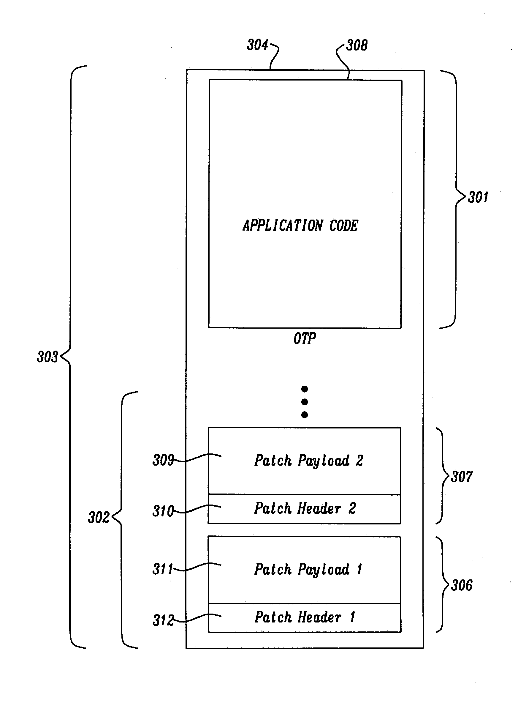
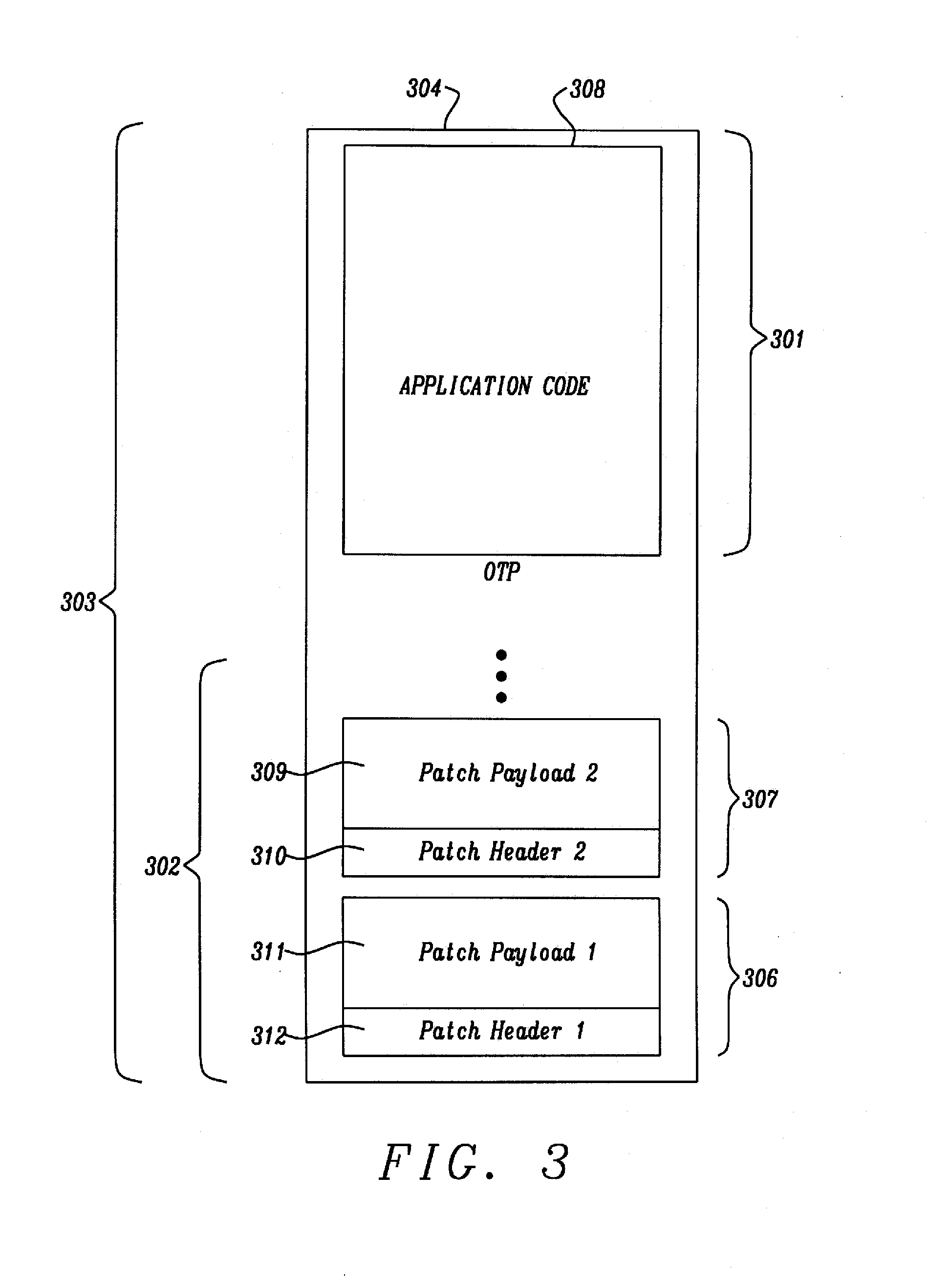
[0044]The techniques disclosed herein may be used, for example, to provide a structured way for implementing patches on an existing firmware residing in an OTP memory that is mirrored into a RAM. The OTP may have a memory layout that is predefined, so that the original data and the patches can be distinguished. For example, predetermined patch areas with specific headers may be provided to identify patch instructions. The program code that processes the patch instructions may be stored in any kind of Non-Volatile (NV) memory, such as a separate read-only memory (ROM), another OTP, or on the same OTP on which the data and the patches are stored.

[0045]The patches may be used, for example, to correct bugs in the firmware within a One Time Programmable (OTP) memory. Also, firmware of a product that is already deployed in the field may be patched using the techniques described herein. Moreover, the need for a pre-defined jump table to specify patchable subroutines may be avoided.

[0046]Th...


PUM


Abstract

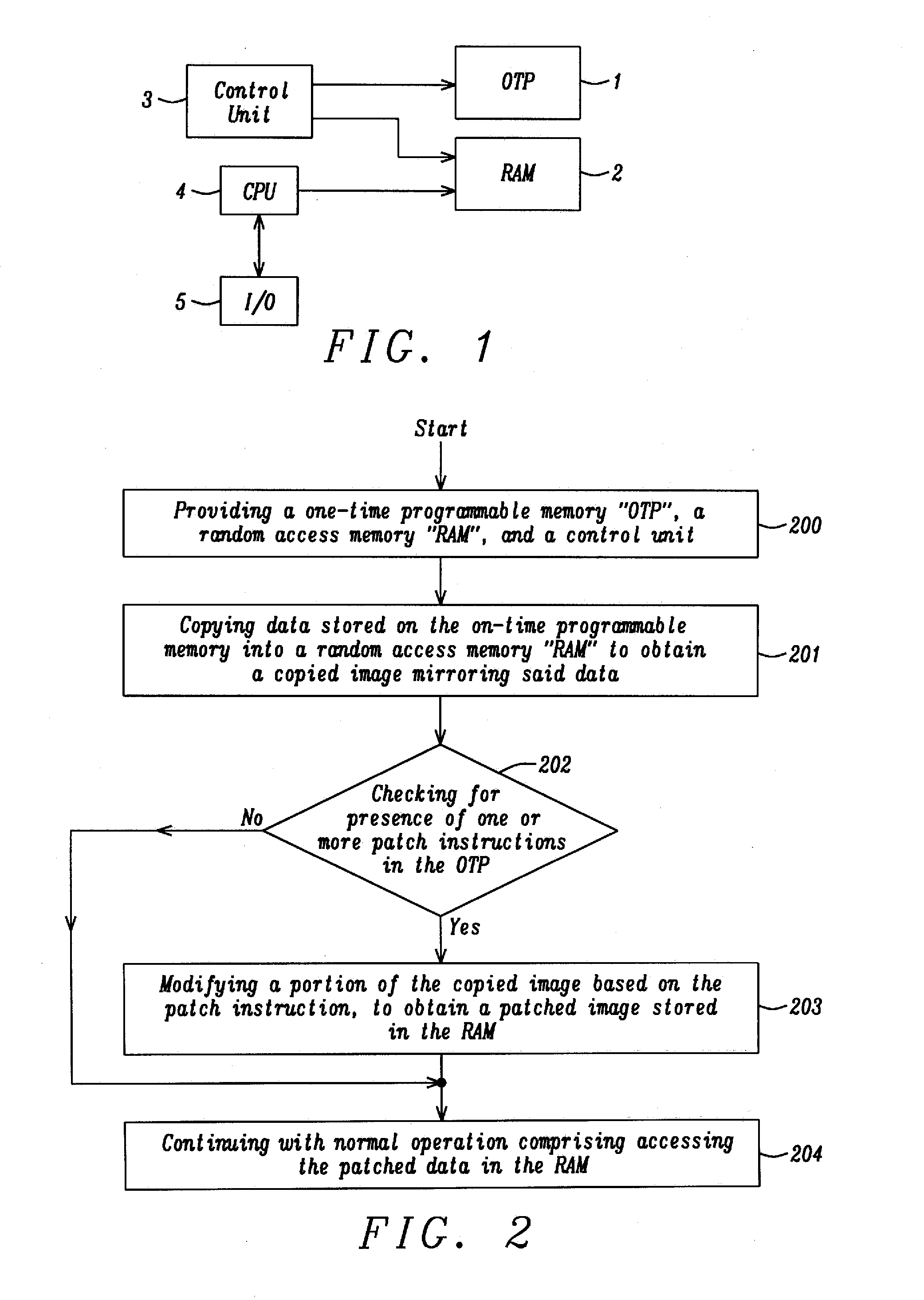
An integrated circuit with a patching function comprises a one-time programmable memory (OTP), a random access memory (RAM), and a control unit. The control unit copies data stored on the OTP into the RAM to obtain a copied image mirroring said data. It checks for presence of one or more patch instructions in the OTP, and, if a patch instruction is found in the OTP, modifies a portion of the copied image based on the patch instruction, to obtain a patched image stored in the RAM. The integrated circuit further comprises a processing unit configured to access the patched image in the RAM. The patch can be provided wirelessly.

Description

TECHNICAL FIELD[0001]The disclosure relates to an integrated circuit with a patching function. The disclosure further relates to a one-time programmable memory (OTP).BACKGROUND[0002]The use of one-time-programmable (OTP) memories as non-volatile storage for code in ultra-low power deeply embedded systems has recently been deployed. OTPs have been used for storing a secret key, system configuration parameters, or as bit flags for various operations within a System on Chip (SoC). Lately, new technologies have enabled the use of larger OTP cells (i.e. 64 Kbytes) for storing the firmware of the System-On-Chip (SoC).[0003]A disadvantage of the OTP is that if a certain memory space is programmed, it cannot be programmed again. Thus, if a bug in the firmware exists, the system cannot be upgraded since the OTP cannot be “corrected”. Another disadvantage is that OTP has relatively high power dissipation when accessed.[0004]Patches for OTP's may be provided in form of a pre-defined jump table...

Claims


Application Information

Patent Timeline
IPC IPC(8): G06F3/06
CPCG06F3/0679G06F3/0629G06F3/0619G06F8/66G06F9/328
Inventor MOSCHOPOULOS, NIKOLAOSCHANOS, DIMITRISSIFNAIOS, IOANNISNINOS, KONSTANTINOSPAPADOPOULOS, DIMITRIOS
Owner DIALOG SEMICONDUCTOR
Learn More