Eureka AIR delivers breakthrough ideas for toughest innovation challenges, trusted by R&D personnel around the world.

Air compressor having chambered piston head

Inactive Publication Date: 2014-09-25
CHOU WEN SAN
View PDF6 Cites 0 Cited by
  • Summary
  • Abstract
  • Description
  • Claims
  • Application Information

AI Technical Summary

Benefits of technology

The present invention provides an air compressor assembly including a piston with a chamber for receiving and buffering pressurized air, allowing the piston to effectively compress the air during the movement or stroke. A valve seat and spring-biased check valve are used to guide the pressurized air and prevent it from flowing backwardly. The piston head has a cavity for receiving air and a groove for allowing air to flow selectively. A spring blade is attached to the piston head to selectively block the groove and prevent air from flowing outwardly. These features enhance the compressing or pumping effect or operation of the air compressor assembly.

Problems solved by technology

However, the solid structure of the piston has no other space or cavity or chamber or compartment formed in the piston head for partially receiving the pressurized air such that the piston has no buffering structure or mechanism formed or provided therein such that the piston may not be effectively moved relative to the cylinder housing and may not be effectively operated to compress or pump the air in the pumping movement or stroke and such that the piston may have a good chance to generate a pressurized air having an over-pressurized condition.

Method used


Image

  • Air compressor having chambered piston head
  • Air compressor having chambered piston head
  • Air compressor having chambered piston head

Examples


Embodiment Construction

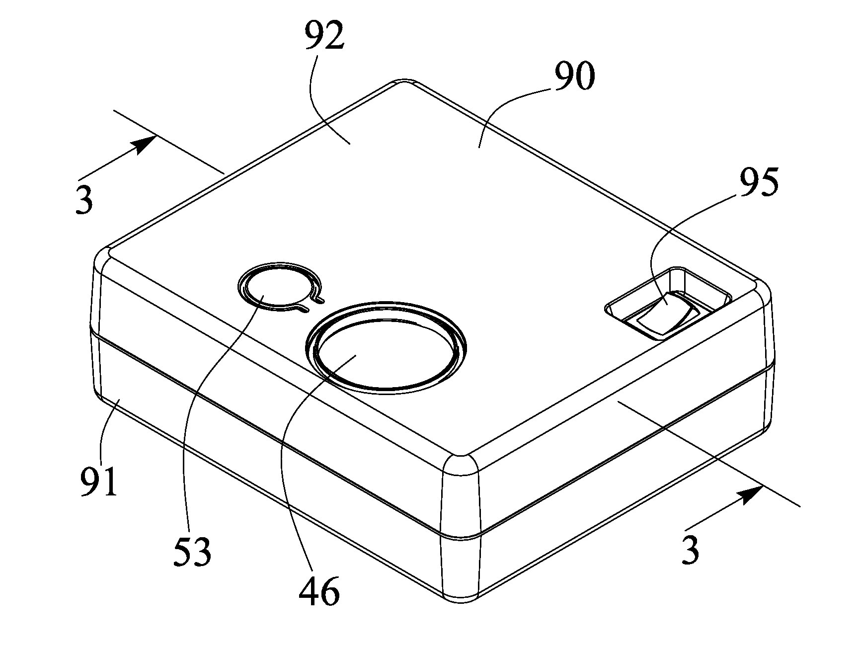
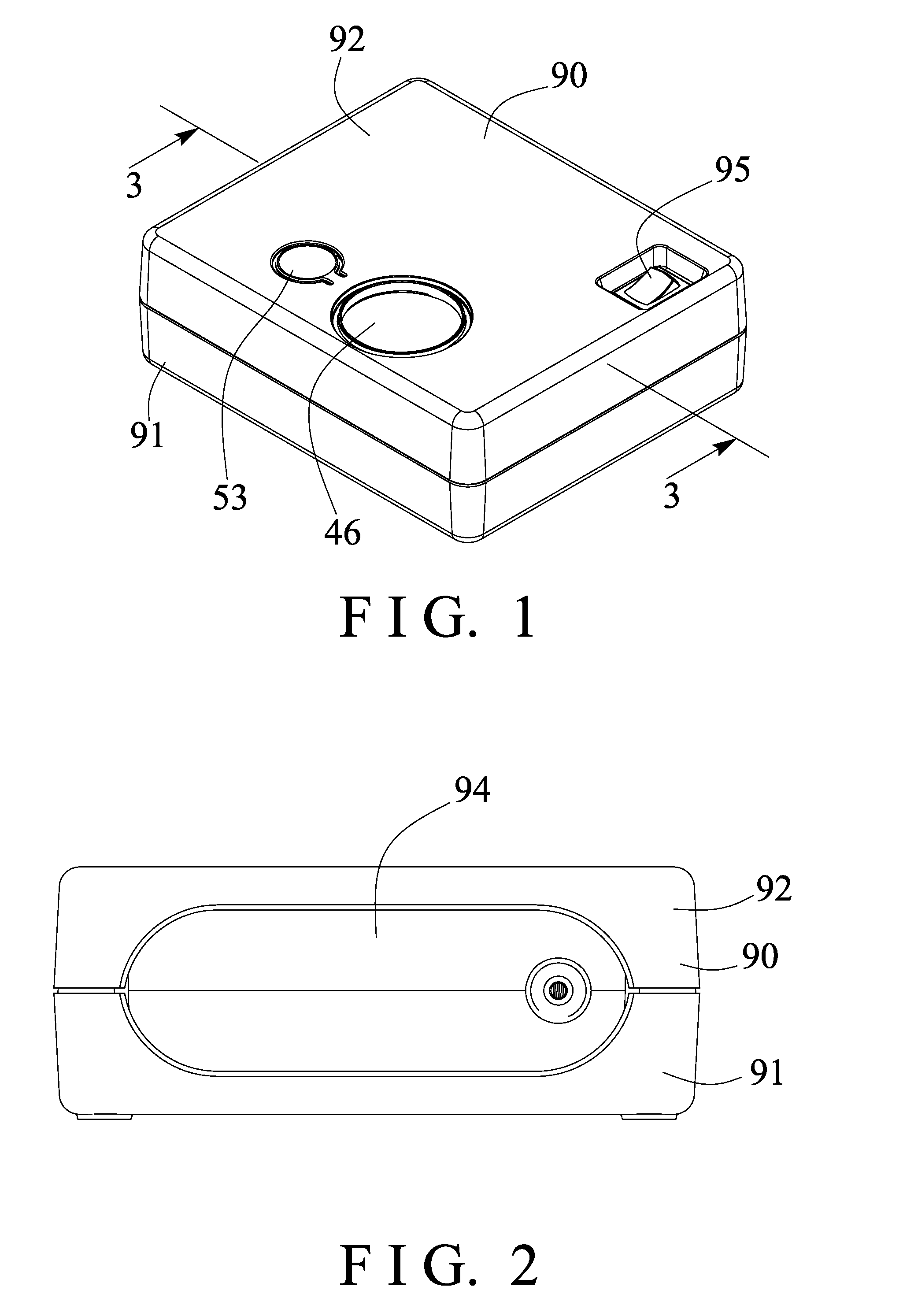
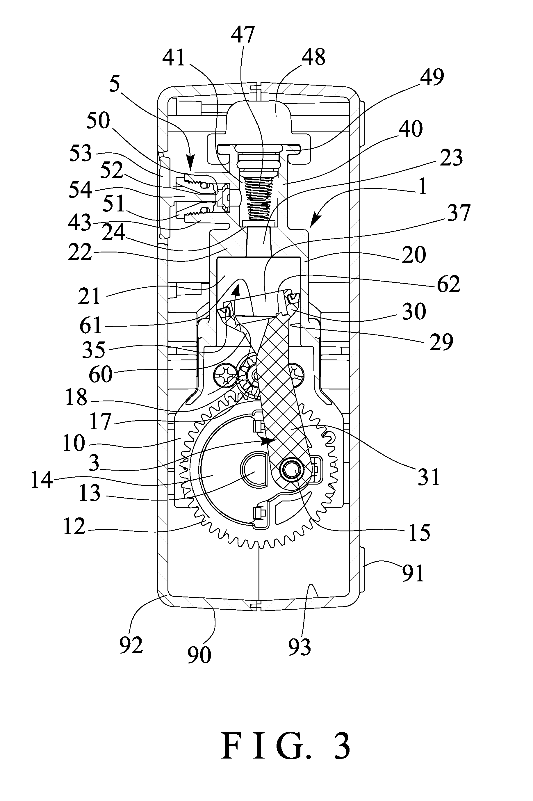
[0028]Referring to the drawings, and initially to FIGS. 1-4, an air compressor assembly in accordance with the present invention comprises an outer receptacle or housing or container 90 including a supporting lower or bottom container member 91 and an upper covering member 92 openably attached or mounted or secured or coupled or anchored or retained or position together to form and to provide a chamber or compartment or space 93 in the container 90 for receiving or accommodating an air compressor device 1. As shown in FIGS. 3-5, the air compressor device 1 includes a supporting base 10 including a supporting plate 11 and a cylinder housing 20 provided on or extended from the supporting plate 11 and preferably, but not necessarily formed integral with the supporting plate 11.

[0029]For example, the supporting plate 11 and the cylinder housing 20 may be formed integral with each other, as shown in FIG. 5, with the molding or mold-injection processes, for example, or alternatively, the ...


PUM


Abstract

An air compressor assembly includes a cylinder housing, an outlet receptacle disposed on the cylinder housing, and a partition having an air passage formed between the cylinder housing and the outlet receptacle, a piston slidably received in the cylinder housing and having a piston rod extended from a piston head for moving relative to the cylinder housing to generate a pressurized air, the piston head includes an upper surface, and includes a cavity formed in the piston head and defined by a bottom surface and an inner peripheral surface and opened upwardly through the upper surface of the piston head and faced and directed toward the partition of the cylinder housing for partially receiving the pressurized air.

Description

BACKGROUND OF THE INVENTION[0001]1. Field of the Invention[0002]The present invention relates to an air compressor assembly, and more particularly to an air compressor assembly including a piston having a chamber or compartment or cavity formed in the piston head for partially receiving the pressurized air and for buffering purposes and for allowing the piston head to effectively compress or pump the air in the pumping movement or stroke and / or for suitably increasing the compressing or pumping effect or operation to the air.[0003]2. Description of the Prior Art[0004]Typical air compressors comprise a cylinder housing attached or secured to a base and having a piston slidably disposed therein, and a motor secured to the base and coupled to the piston of the cylinder housing for actuating or driving the piston of the cylinder housing in a reciprocating action, in order to generate a pressurized air of a greater air pressure and a decreased flowing quantity and for supplying the press...

Claims


Application Information

Patent Timeline
IPC IPC(8): F04B39/00
CPCF04B39/0005F02K1/82F23R3/60F02K1/80
Inventor CHOU, WEN SAN
Owner CHOU WEN SAN
Why Eureka
Eureka Blog
Learn More