Automated Coupler Positioning Device

a technology for positioning devices and couplers, which is applied in the direction of railway couplings, railway components, railway coupling accessories, etc., can solve the problems that conventional coupler positioning devices cannot center the coupler, and the existing design of coupler positioning devices cannot adapt to automatically align the couplers of adjacent railway cars

Active Publication Date: 2014-09-25
WABTEC HLDG CORP
View PDF13 Cites 23 Cited by
  • Summary
  • Abstract
  • Description
  • Claims
  • Application Information

AI Technical Summary

Benefits of technology

[0010]In accordance with another embodiment, the automated coupler positioning device is adapted for performing an automated positioning operation of the coupler relative to an adjacent coupler without requiring manual assistance. In another

Problems solved by technology

None of the positioning devices, discussed above, uses an automated means for positioning the coupler at an off-center position to allow the coupler to couple to an adjacent coupler on a curved section of track.
Existing designs for coupler positioni

Method used


Image

  • Automated Coupler Positioning Device
  • Automated Coupler Positioning Device
  • Automated Coupler Positioning Device

Examples


Embodiment Construction

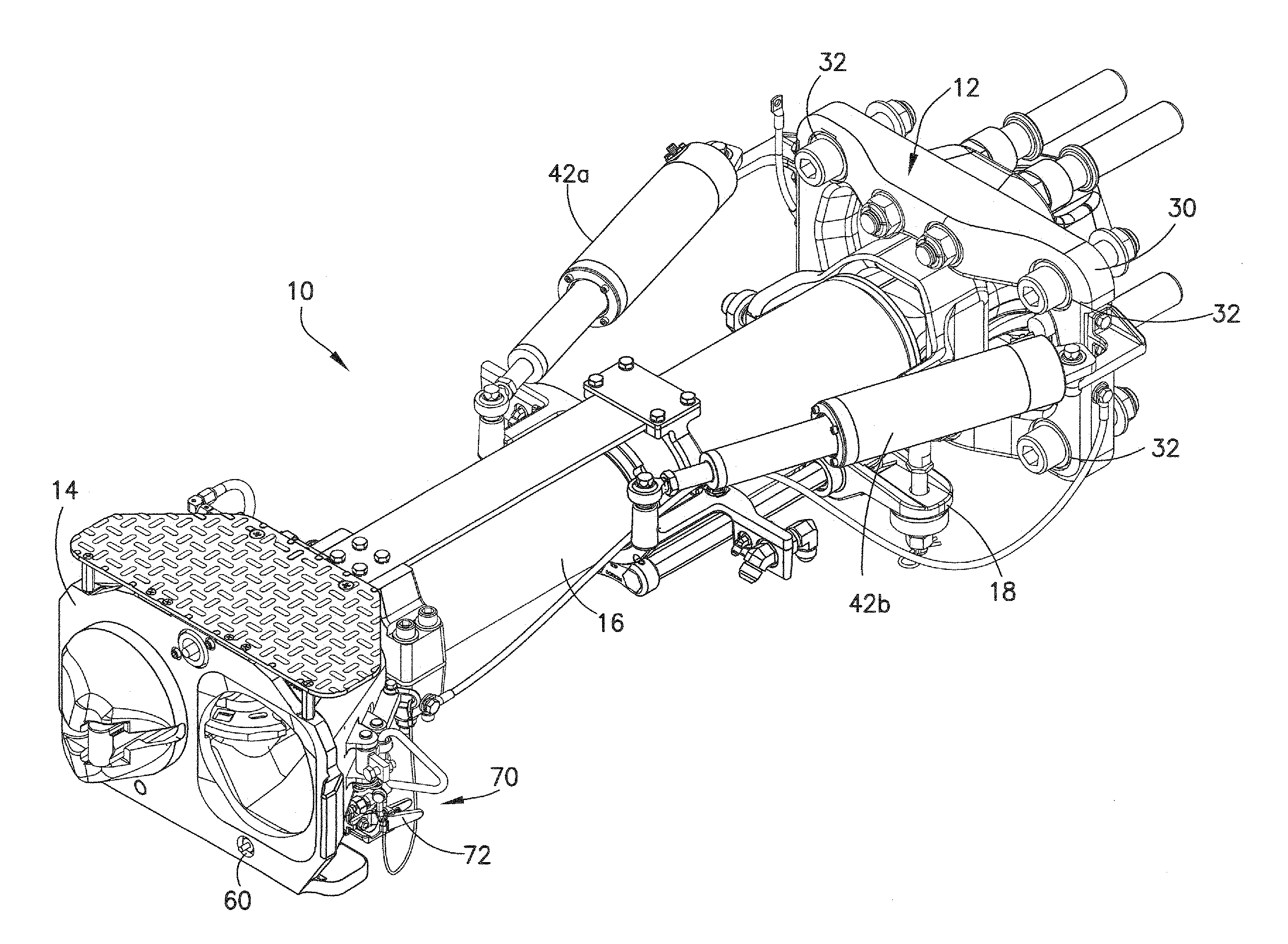
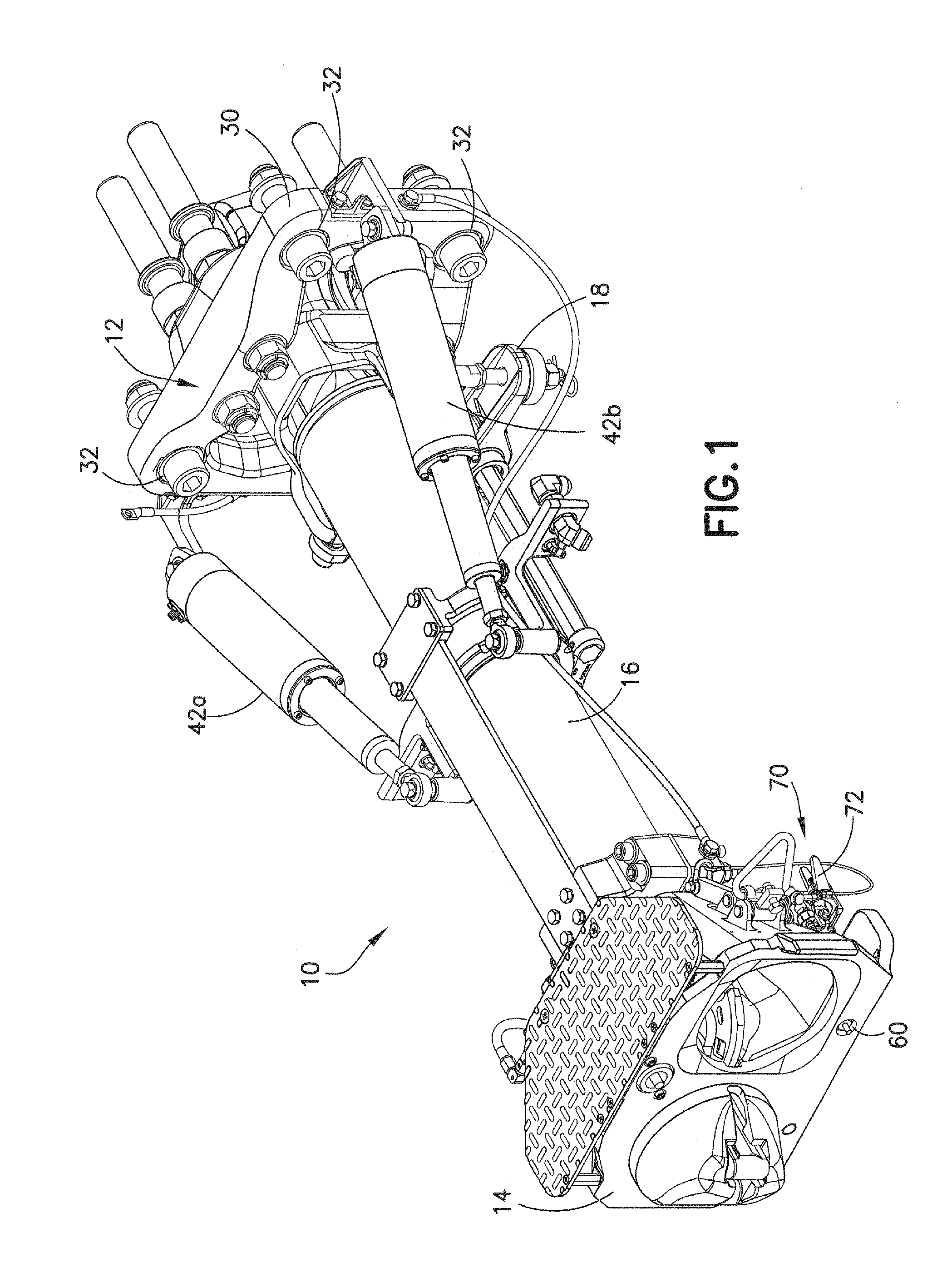
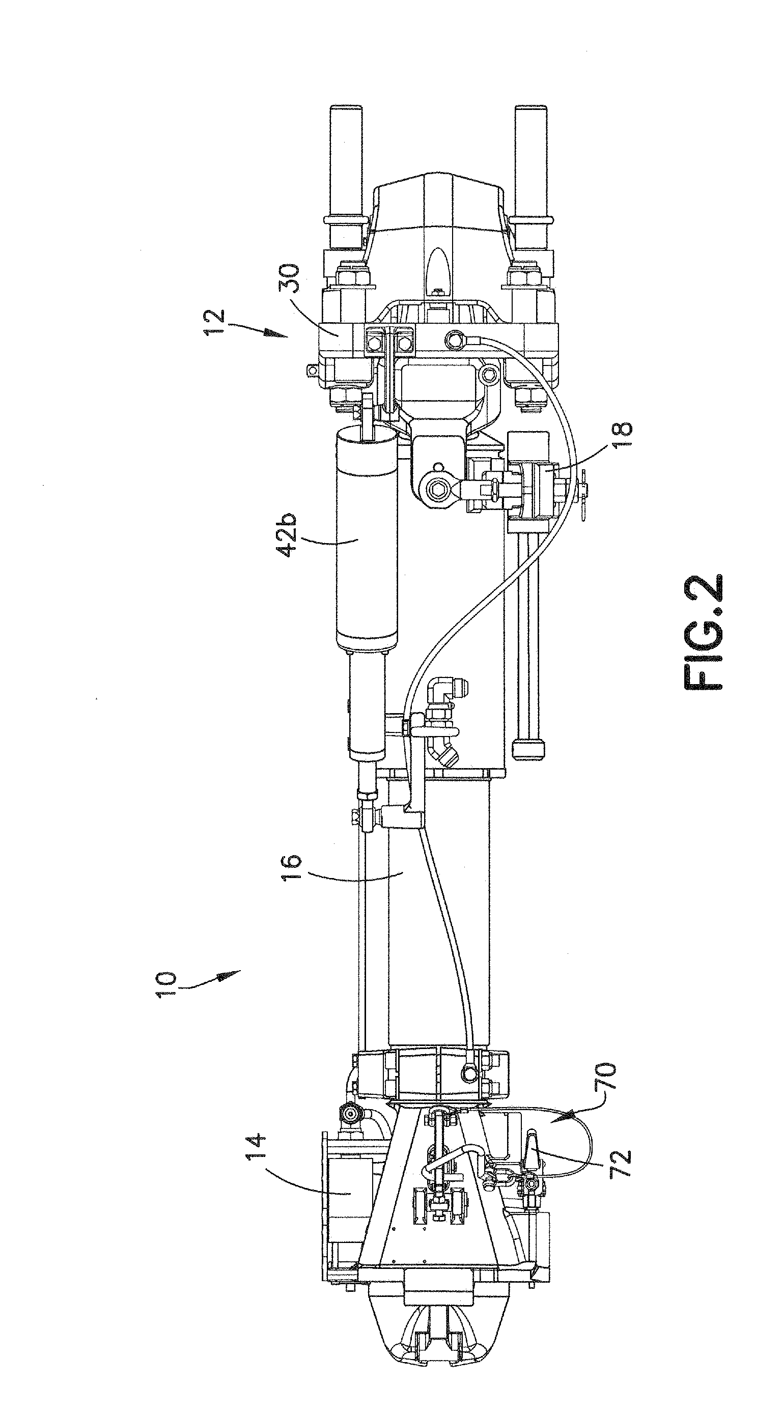
[0029]For purposes of the description hereinafter, the terms “upper”, “lower”, “right”, “left”, “vertical”, “horizontal”, “top”, “bottom”, “lateral”, “longitudinal”, and derivatives thereof, shall relate to the invention as it is oriented in the drawing figures. However, it is to be understood that the invention may assume alternative variations and step sequences, except where expressly specified to the contrary. It is also to be understood that the specific devices and processes illustrated in the attached drawings, and described in the following specification, are simply exemplary embodiments of the invention. Hence, specific dimensions and other physical characteristics related to the embodiments disclosed herein are not to be considered as limiting.

[0030]Referring to the drawings in which like reference characters refer to like parts throughout the several views thereof, the present disclosure is generally directed to a railway car coupler having an automated coupler positionin...


PUM


Abstract

A coupler for a railway car including a coupler anchor, a coupler mechanism pivotable relative to the coupler anchor from an on-center position to an off-center position in a substantially horizontal plane, and a coupler positioning device for pivoting the coupler mechanism relative to the coupler anchor. The coupler positioning device includes a controller adapted for receiving signal information from a bogie relating to an angular position of the bogie relative to a body of the railway car, and at least one pneumatic cylinder for pivoting the coupler mechanism. The controller controls the operation of the at least one pneumatic cylinder in response to the signal information received from the bogie.

Description

CROSS REFERENCE TO RELATED APPLICATIONS[0001]This application claims the benefit of U.S. Provisional Patent Application No. 61 / 804,470, filed Mar. 22, 2013, and entitled “Automated Coupler Positioning Device”, the disclosure of which is hereby incorporated in its entirety by reference.BACKGROUND OF THE INVENTION[0002]1. Field of the Invention[0003]The present disclosure is directed to couplers for railway cars, and more particularly, to a device for automatic horizontal positioning of a railway car coupler.[0004]2. Description of Related Art[0005]Railway cars include couplers for connecting adjacent cars to each other to form a train composition. Each coupler is adapted to swing within a predetermined angular range in a horizontal direction to facilitate car coupling and movement on a curved track. Adjoining car couplers are generally aligned to be on-center with the longitudinal axis of the railway car during a car coupling procedure. Due to variations in sizes of the cars and the ...

Claims


Application Information

Patent Timeline
IPC IPC(8): B61G7/12
CPCB61G7/12B61G5/08B61G3/20
Inventor PECKHAM, JASON DANIELSWINDLER, WILLIAM CLAYBROWN, KEVIN SCOTT
Owner WABTEC HLDG CORP
Why Eureka
Try Eureka