
Vehicle side airbag device

Active Publication Date: 2014-09-25
TOYOTA JIDOSHA KK
View PDF19 Cites 11 Cited by
  • Summary
  • Abstract
  • Description
  • Claims
  • Application Information

AI Technical Summary

Benefits of technology

The invention is a car side airbag that can quickly inflate and deploy in a narrow space between the pillar of the car and a person's seat. It can also handle steps between the pillar and a door trim.

Problems solved by technology

Also, when the vehicle is involved in a side collision with a pole or the like and a step forms between the pillar garnish and the door trim, the step is covered by the deployment guiding member, so the side airbag will not easily get caught on the step.

Method used


Image

  • Vehicle side airbag device
  • Vehicle side airbag device
  • Vehicle side airbag device

Examples


first example embodiment

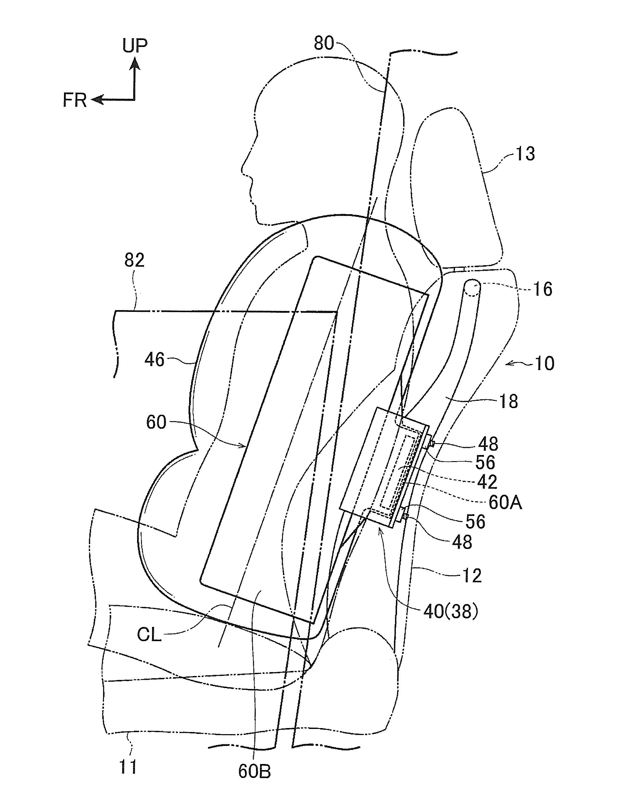
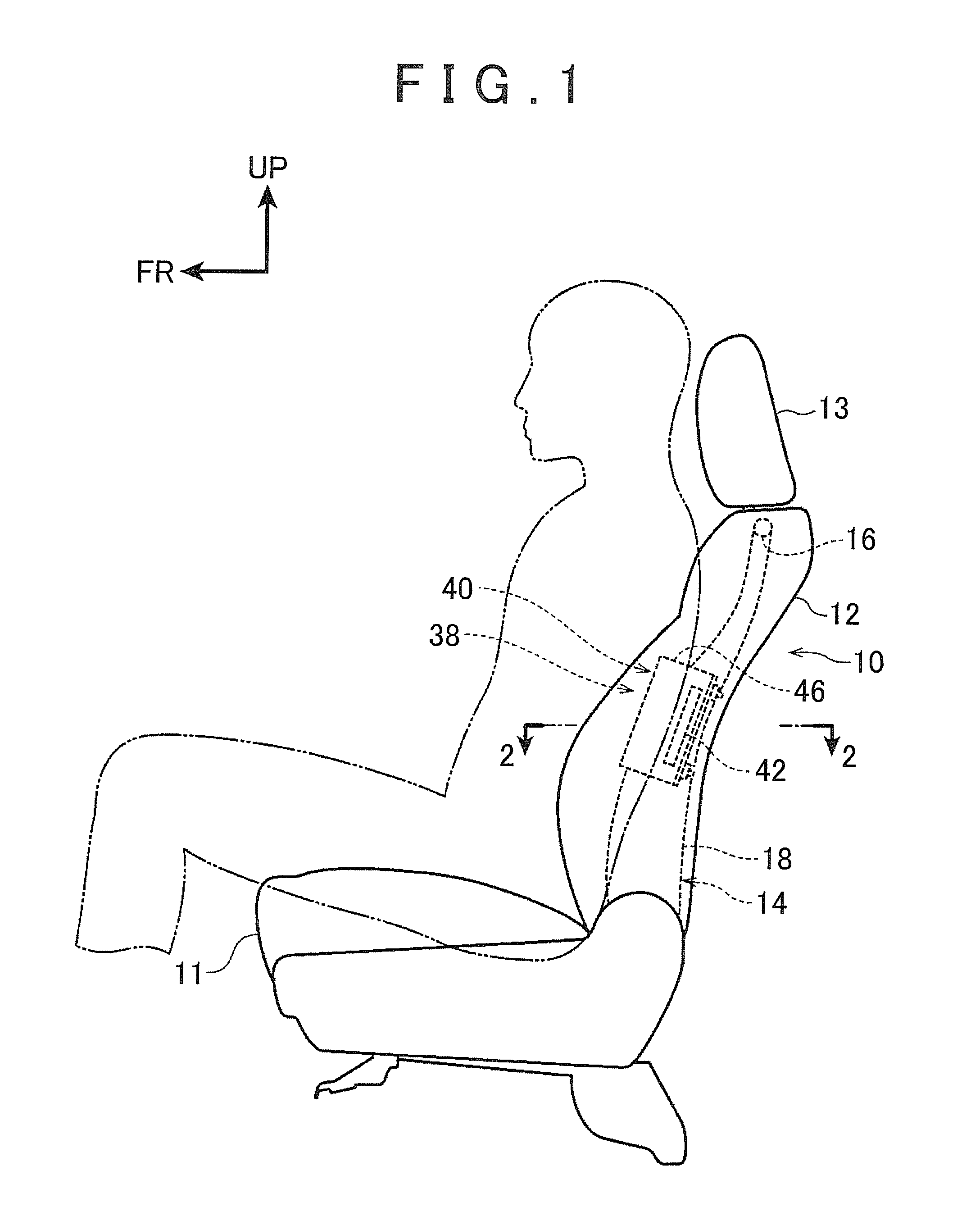
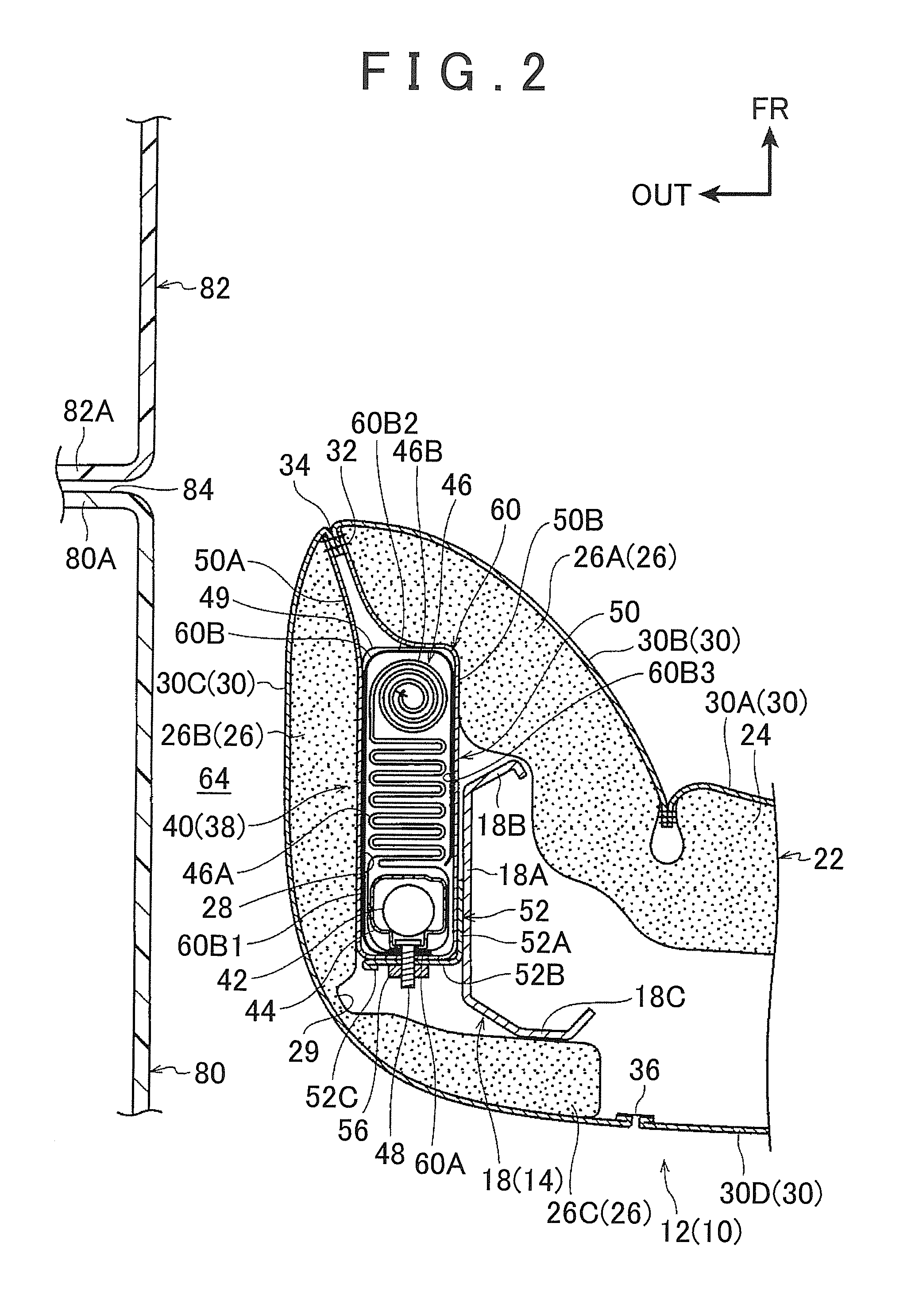
[0051]A vehicle side airbag according a first example embodiment of the invention will now be described with reference to FIGS. 1 to 6. In the drawings, arrow FR indicates a vehicle front side, arrow UP indicates a vehicle upward side, and arrow IN indicates an inside in a vehicle width direction.

[0052]As shown in FIG. 1, a vehicle seat 10 includes a seat cushion 11 on which an occupant sits, a seatback 12 that is tiltably provided upright on a rear end portion of this seat cushion 11 and supports an upper body of the occupant, and a headrest 13 that is provided on an upper end portion of the seatback 12 and supports a head of the occupant. Also, as shown in FIG. 2, a center pillar garnish 80 that lines an inside in a vehicle width direction of a center pillar is arranged on an outside in the vehicle width direction of the seatback 12 of the vehicle seat 10. Furthermore, a door trim 82 that lines an inside in the vehicle width direction of a door inner panel of a front side door is ...

second example embodiment

[0080]Hereinafter, a vehicle side airbag device according to a second example embodiment of the invention will be described with reference to FIGS. 7B, 7C, and 7D. Component parts that are similar to those in the first example embodiment described above will be denoted by like reference characters and descriptions of those component parts will be omitted.

[0081]FIG. 7A is a comparative view of the structure of the side airbag device 38 according to the first example embodiment described above. FIGS. 7B to 7D are views of the side airbag device according to the second example embodiment to which structure that differs from that shown in FIG. 7A has been added.

[0082]First, in the example embodiment shown in FIG. 7B, the airbag module 40 is provided with a resin airbag case 100. This airbag case 100 has a thin rectangular parallelepiped shape, and is able to be opened and closed. Also, the airbag case 100 employs an opening and closing structure by pawl engagement at a corner portion 10...


PUM


Abstract

A deployment guiding cloth is wound from an outside in the vehicle width direction, on an outer peripheral portion of a folded side airbag. This deployment guiding cloth extends toward a vehicle front side and is interposed between the side airbag that is partially deployed and a vehicle cabin side portion (a center pillar garnish and a door trim) before the side airbag is fully deployed.

Description

INCORPORATION BY REFERENCE [0001]The disclosure of Japanese Patent Application No. 2013-060308 filed on Mar. 22, 2013 including the specification, drawings and abstract is incorporated herein by reference in its entirety.BACKGROUND OF THE INVENTION[0002]1. Field of the Invention[0003]The invention relates to a vehicle side airbag device.[0004]2. Description of Related Art[0005]Japanese Patent Application Publication No. 2011-240807 (JP 2011-240807 A) describes technology relating to a vehicle side airbag device. More specifically, a side airbag having a two-chamber structure is used which, when a side collision occurs, inflates and deploys in a general V-shape when viewed from above by a front portion that is pressed against from diagonally in front toward the chest of an occupant, and a rear portion that is pressed against from diagonally behind.[0006]However, this related art has various problems. First, when a large occupant (i.e., an occupant with a large frame (build)) sits in ...

Claims


Application Information

Patent Timeline
IPC IPC(8): B60R21/207
CPCB60R21/207B60R2021/161B60R2021/23146B60R2021/2076B60R21/201
Inventor AKIYAMA, FUMITO
Owner TOYOTA JIDOSHA KK
Learn More