A method to determine an alignment errors in image data and performing in-track alignment errors correction using test pattern

a technology of image data and alignment errors, applied in the field of digital printing, can solve the problems of alignment errors, alignment errors, alignment errors, etc., and achieve the effect of reducing the visibility of objectionable artifacts and reducing the alignment errors

Active Publication Date: 2014-09-25
EASTMAN KODAK CO
View PDF1 Cites 19 Cited by
  • Summary
  • Abstract
  • Description
  • Claims
  • Application Information

AI Technical Summary

Benefits of technology

[0031]This invention has the advantage that alignment errors can be reduced at swath boundaries, thereby reducing the visibility of objectionable artifacts.
[0032]It has the additional advantage that the method is insensitive to variability in magnification of the digital imaging system used to digitize the printed test pattern.

Problems solved by technology

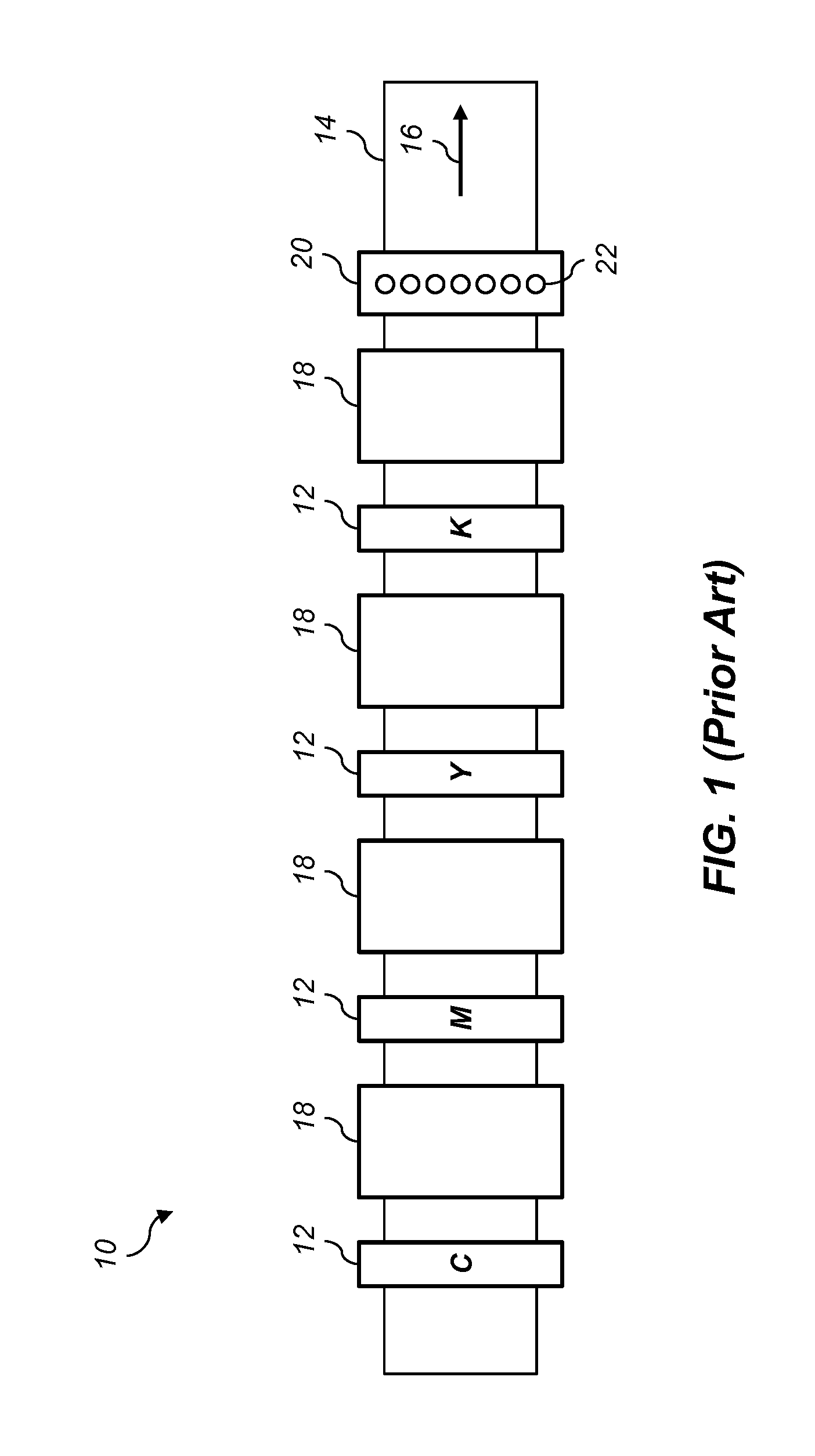
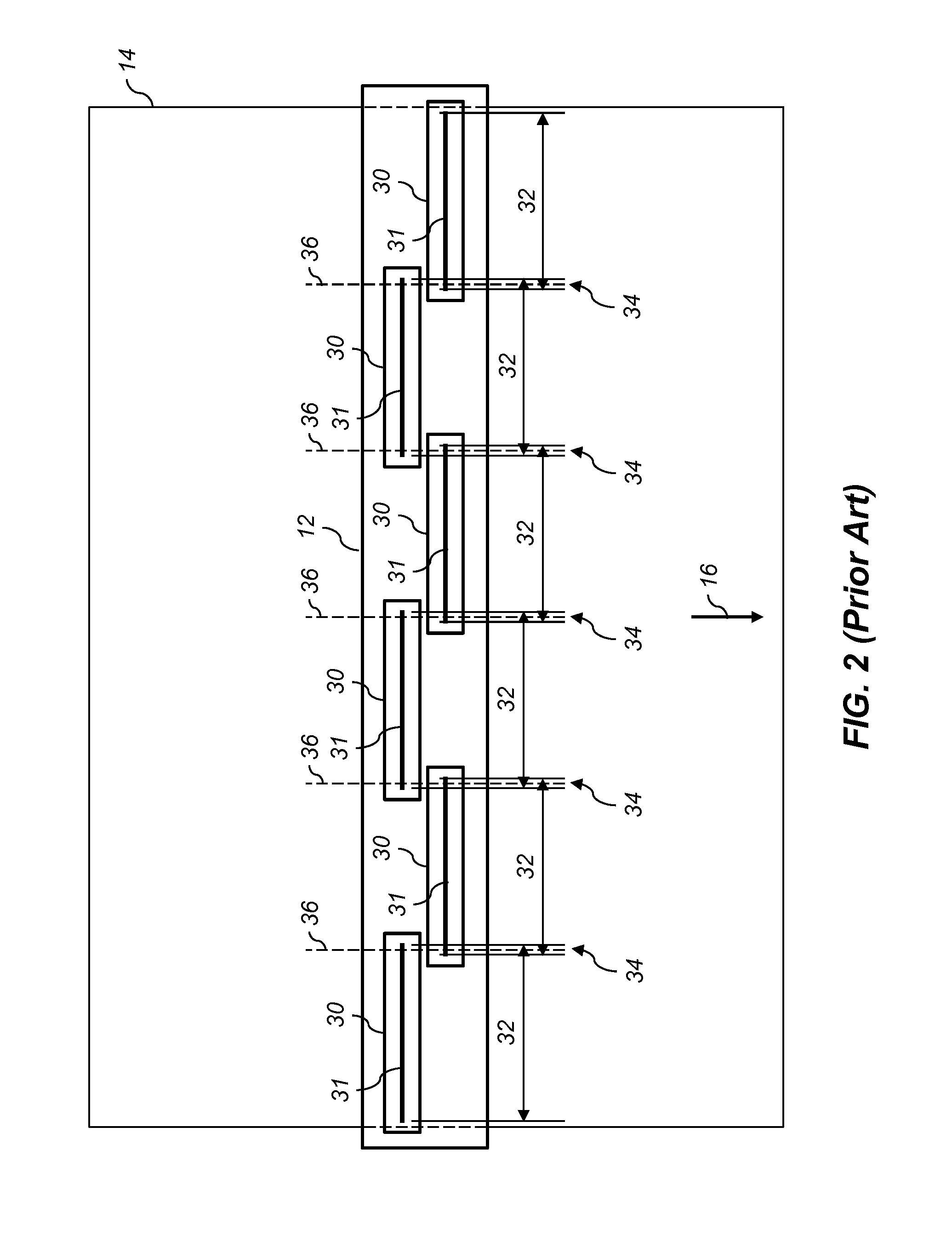
One problem which is common in printing systems 10 that include a plurality of printheads 30 is alignment of the image data printed by the different printheads 30.
There are a variety of different types of alignment errors that can occur.
These color-to-color alignment errors can occur in either or both of the in-track direction or the cross-track direction.
The alignment errors can result from a variety of different causes.
In other cases, alignment errors can result from interactions between the printing system 10 and the environment (e.g., airflow perturbations can cause ink drops to be misdirected in inkjet printing systems).
Due to mechanical tolerances in the manufacturing process, it may be difficult to maintain an accurate alignment between the printheads 30 in a printing module 12.
Any such alignment errors can produce visible artifacts in the printed image.
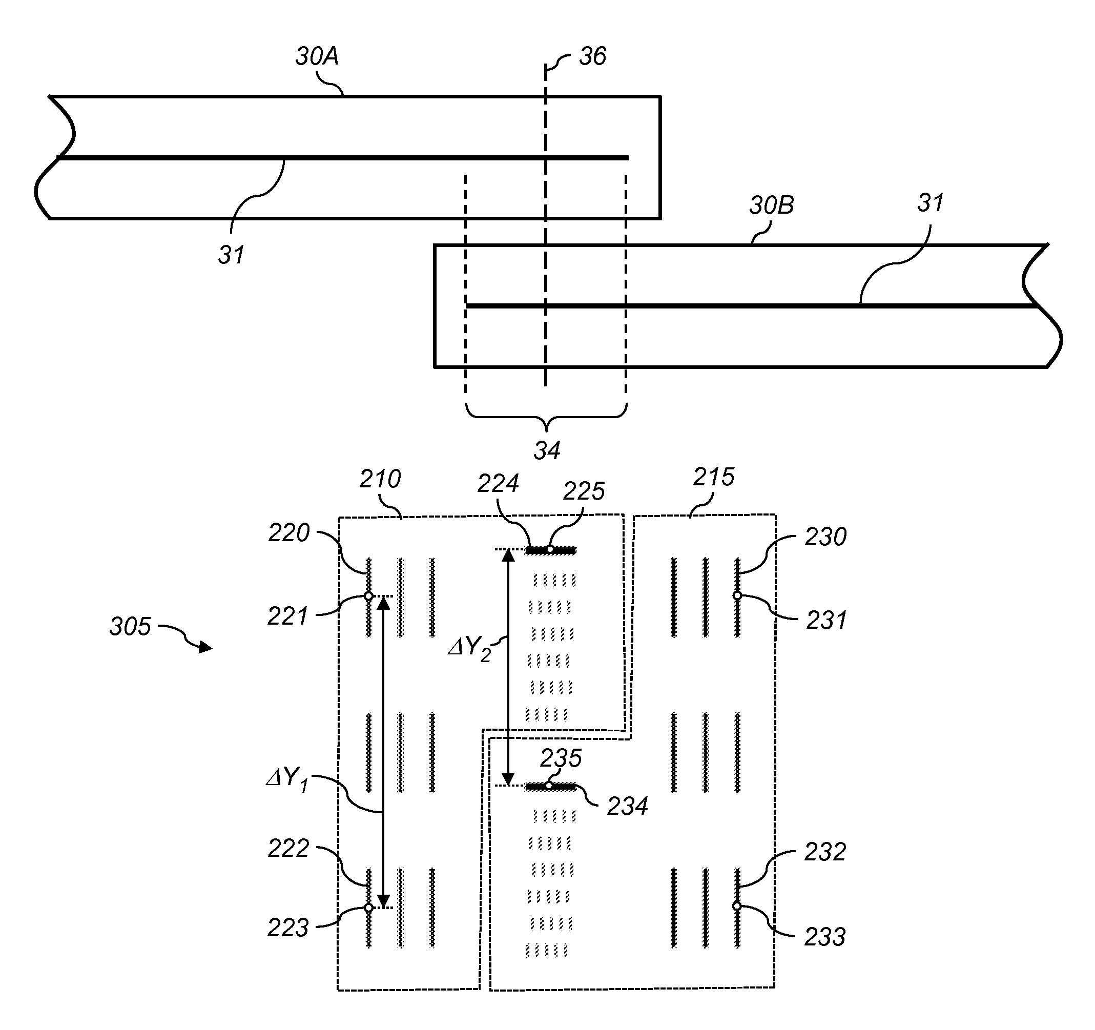
Alignment errors between the printheads 30 in the cross-track direction can result in artifacts being produced at the boundaries between the printheads (e.g., dark streaks where the multiple nozzles print at the same location, or light streaks where no nozzles print at a particular location).
Alignment errors between the printheads 30 in the in-track direction can result in artifacts being produced where portions of a linear feature in the image that spans the overlap region don't align with each other and appear to be broken.
Such a system requires extremely high cost encoders to provide the resolution needed for the registration demands of a printer system.
It also is subject to errors associated with slip or coupling between the motor and the motion of the paper through the print zone.
This system is also very susceptible to errors produced by variations in motor speed such as wow and flutter.
One limitation of this method is that the necessary separation between the first test mark and the second test mark in the cross-track direction means that the in-track alignment of the printed image data will only be perfectly corrected at those cross-track positions.
This does not ensure that the printed image data will be perfectly aligned at the boundaries between the printheads (e.g., at centerlines 36 in FIG. 2).

Method used


Image

  • A method to determine an alignment errors in image data and performing in-track alignment errors correction using test pattern
  • A method to determine an alignment errors in image data and performing in-track alignment errors correction using test pattern
  • A method to determine an alignment errors in image data and performing in-track alignment errors correction using test pattern

Examples


Embodiment Construction

[0042]In the following description, some embodiments of the present invention will be described in terms that would ordinarily be implemented as software programs. Those skilled in the art will readily recognize that the equivalent of such software may also be constructed in hardware. Because image manipulation algorithms and systems are well known, the present description will be directed in particular to algorithms and systems forming part of, or cooperating more directly with, the method in accordance with the present invention. Other aspects of such algorithms and systems, together with hardware and software for producing and otherwise processing the image signals involved therewith, not specifically shown or described herein may be selected from such systems, algorithms, components, and elements known in the art. Given the system as described according to the invention in the following, software not specifically shown, suggested, or described herein that is useful for implement...


PUM


Abstract

A method for aligning image data printed on a receiver medium in a multi-printhead printer that includes printing a test pattern including features separated by predefined test pattern feature separations, where some features are printed with a first printhead and some features printed with a second printhead. An image of the printed test pattern is analyzed to determine a first camera pixel separation between two features printed with the first printhead, which is used to determine a camera scale factor. The camera scale factor is used to scale a second camera pixel separation between a feature printed with first printhead and a feature printed with the second printhead. The scaled second camera pixel separation is compared to a corresponding test pattern feature separation to determine an alignment error, which is used to adjust the alignment of the image data printed with at least one of the printheads.

Description

CROSS-REFERENCE TO RELATED APPLICATIONS[0001]Reference is made to commonly assigned, co-pending U.S. patent application Ser. No. ______ (Docket K001503), entitled: “Multi-printhead printer alignment”, by Enge, which is incorporated herein by reference.FIELD OF THE INVENTION[0002]This invention pertains to the field of digital printing and more particularly to a method for aligning printed image data in a multi-printhead printer.BACKGROUND OF THE INVENTION[0003]FIG. 1 shows a diagram illustrating an exemplary multi-channel digital printing system 10 for printing on a web of receiver medium 14. The printing system 10 includes a plurality of printing modules 12, each adapted to print image data for an image plane corresponding to a different color channel. In some printing systems 10, the printing modules 12 are inkjet printing modules adapted to print drops of ink onto the receiver medium 14 through an array of inkjet nozzles. In other cases, the printing modules 12 can be electrophot...

Claims


Application Information

Patent Timeline
Patent Type & Authority Applications(United States)
IPC IPC(8): G06K15/02
CPCG06K15/027B41J2/2135B41J2/2146B41J3/543B41J2029/3935
Inventor ENGE, JAMES MICHAEL
Owner EASTMAN KODAK CO
Why Eureka
Try Eureka