Lamp Tubes

Inactive Publication Date: 2014-09-25
JUSTING TECH
View PDF4 Cites 13 Cited by
  • Summary
  • Abstract
  • Description
  • Claims
  • Application Information

AI Technical Summary

Benefits of technology

[0020]This invention aims at providing a lamp tube comprising a tube body, a circuit board and two end covers, the lamp tube facilitates a user to utilize a simple inserting action to form a reliable electrical condu

Problems solved by technology

As the fluorescent lamp tubes contain therein a small amount of mercury, one has to be extremely careful when taking or mounting the fluorescent lamp because leakage of the mercury within the lamp will damage the environment and may cause intoxication to a human being in contact therewith.
Moreover, although the conventional fluorescent lamp is relatively cheap, it has the drawback that as a waste, there might be mercury pollution, or it may easily be broken due to its glass nature.
However, current LED

Method used


Image

  • Lamp Tubes
  • Lamp Tubes
  • Lamp Tubes

Examples


first embodiment

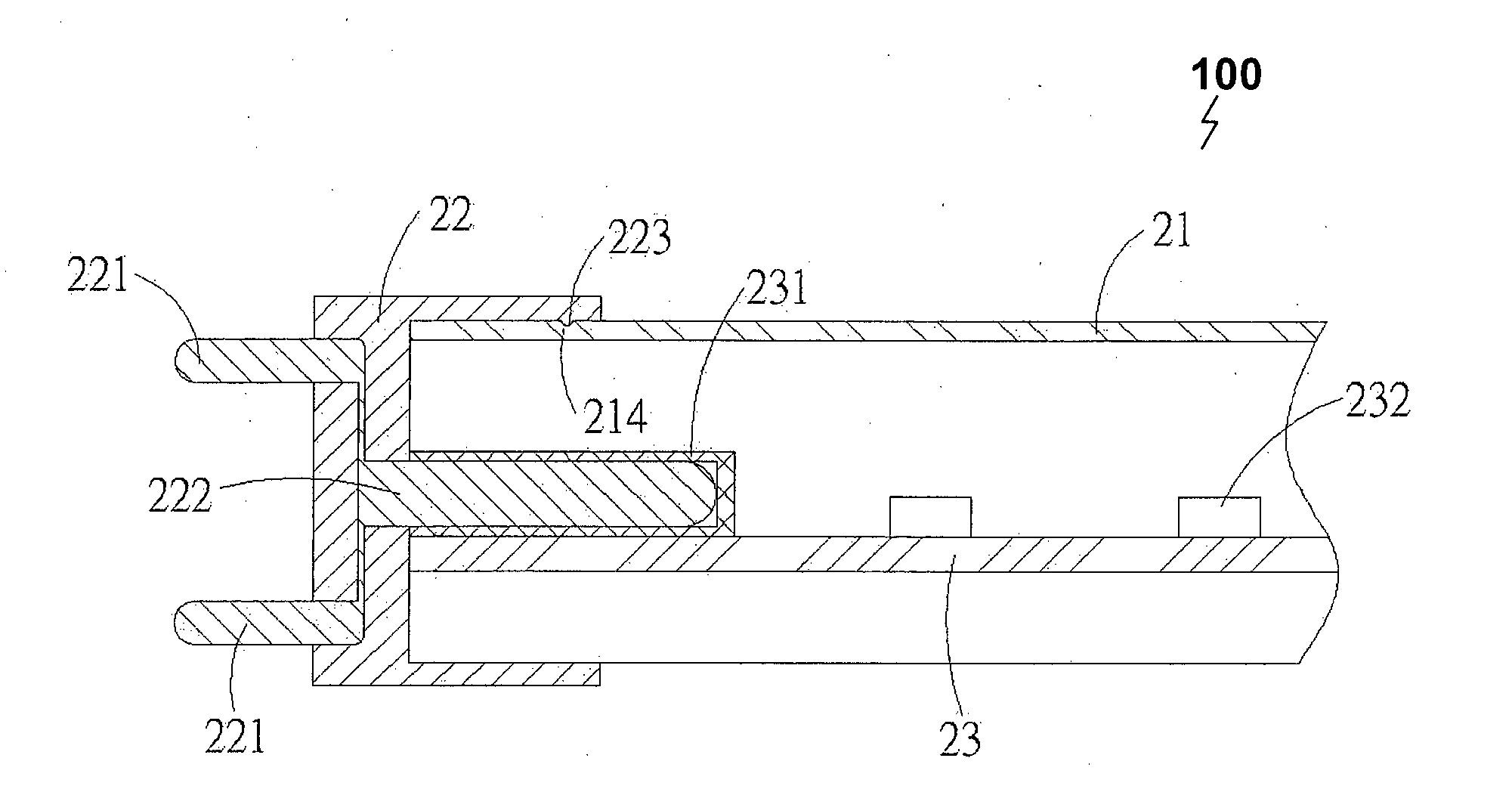
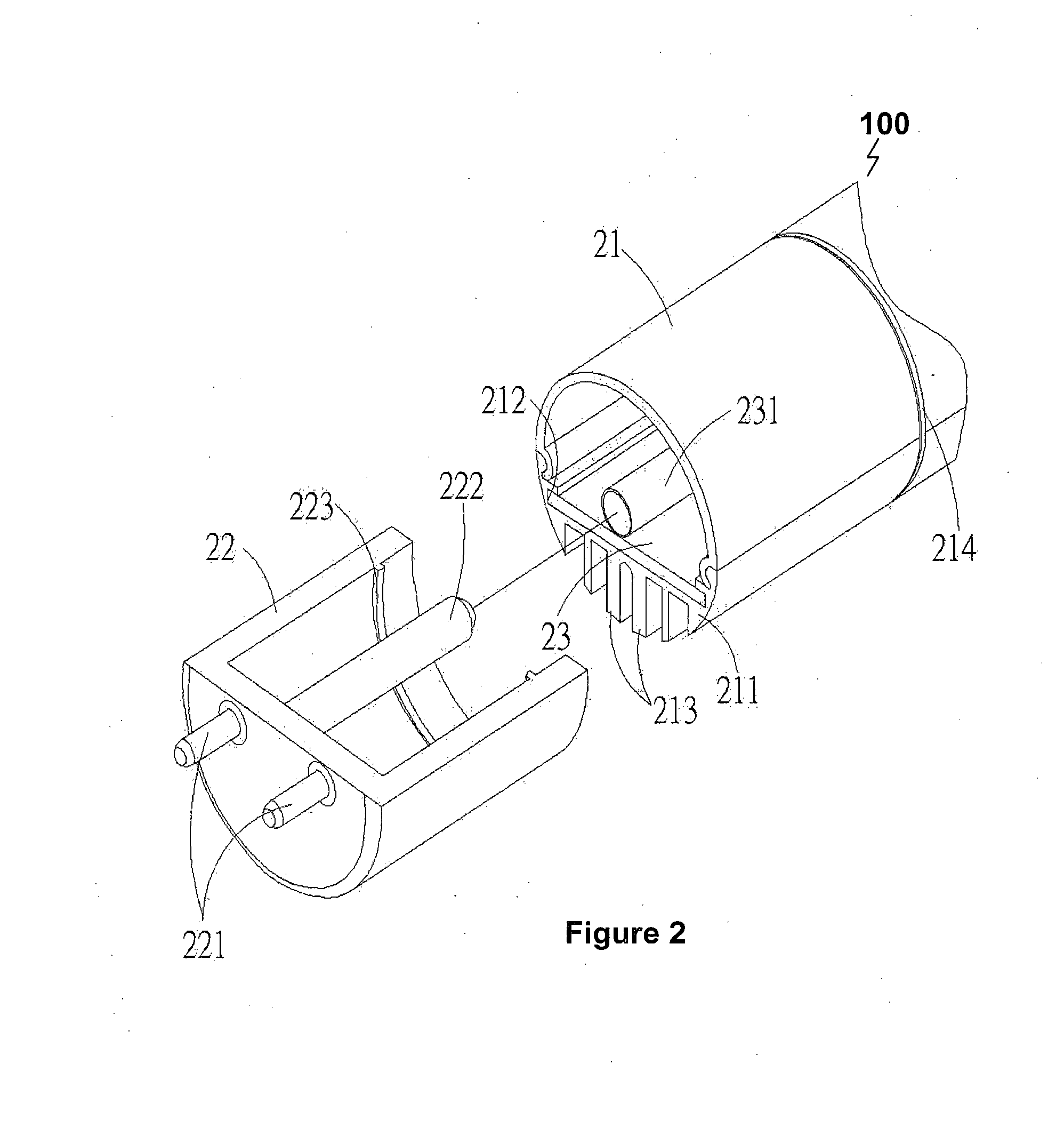
[0050]In accordance with the present invention there is a lamp tube 100. FIG. 2 illustrates the exploded structural diagram of the lamp tube 100. Lamp tube 100 comprises a tube body 21 and two end covers 22 (illustrated as a cut-open section). Lamp tube 100 is adapted to receive a circuit board 23.

[0051]At the inner side of the tube body 21 there is provided a seat body 211. The seat body 211 is provided with a positioning slot 212 for placement of the circuit board 23. In the embodiment shown in the FIGS. 2 to 4, the tube body 21 is shaped as a circular tube. The lower edge of the tube body 21 may be formed as a plurality of heat-dissipating fins 213 for heat dissipation. In operation when the circuit board 23 is inserted into the tube body 21 and positioning slot 212, the circuit board 23 is in thermal contact with the heat-dissipating fins 213 for heat-dissipation.

[0052]In normal operation, the end covers 22 are respectively disposed at the two ends of the tube body 21. Each end ...

second embodiment

[0061]In accordance with the invention, wherein like numerals reference like parts, there is illustrated in FIG. 5 an exploded structural diagram of a lamp tube 500 of this invention. The side sectional view of the LED lamp tube 500 is illustrated in FIG. 6, and the front / end sectional view of the LED lamp tube 500 is illustrated in FIG. 7. The LED lamp tube 500 comprises a tube body 21, two end covers 22, a circuit board 23 and a sliding positioning structure 240.

[0062]At the inner side of the tube body 21 there is provided a positioning slot 211 for placement of the circuit board 23.

[0063]In operation, the end covers 22 are respectively disposed at two ends of the tube body 21. Each end cover 22 is provided with two electrical terminals 221, and at the inner side of each end cover 22 there is provided an electrically conducting terminal 222. The electrically conducting terminal 222 is connected to the electrical terminals 221, wherein the electrical terminals 221 are integrally fa...

third embodiment

[0068]In accordance with the invention where like numerals reference like parts there is provided a lamp tube 1000, the structural schematic diagram of which is illustrated in FIGS. 11 to 13. The LED lamp tube 1000 includes: a tube body 21 and two end covers 22. Lamp tube 1000 is adapted to receive a circuit board 23.

[0069]At the inner side of the tube body 21 there is provided a seat body 211. The seat body 211 is provided with a positioning slot 212 for placement of the circuit board 23. In the embodiment shown in the figure, the lamp tube 21 is circular-tube shaped, and at a lower edge of the tube body 21 there are formed a plurality of heat-dissipating fins 213 for heat dissipation. In normal operation, the end covers 22 are respectively disposed at two ends of the lamp tube 21. Each end cover 22 is provided with two electrical terminals 221, and at the inner side of each end cover 22 there is provided an electrically conducting terminal 222. The electrically conducting terminal...


PUM


Abstract

A lamp comprising a lamp tube, the lamp tube having a positioning slot formed on an inner side of the lamp tube for receiving a circuit board; two end covers installable at both ends of the lamp tube; each end cover comprises two electrical terminals for receiving electrical power from a source, and each end cover includes a conductive terminal disposed on an inner side of the end cover and coupled to the electrical terminal; and a circuit board arranged to be positioned in the positioning slot, the circuit board includes two sockets disposed at both ends of the circuit board; wherein in operation the conductive terminal of each end cover is plugged into the respective socket to conduct electric power.

Description

CROSS-REFERENCE TO RELATED APPLICATIONS[0001]This application claims priority from the following Taiwan and China patent applications:[0002]TW 100213133;[0003]TW 100125250;[0004]TW 101200372;[0005]TW 101200373;[0006]CN 201220193853.8;[0007]CN 201210133522.X;[0008]CN 201220193742.7; and[0009]CN 201220193702.2the entire contents of which are incorporated herein by reference.FIELD OF THE INVENTION[0010]The present invention relates to lamps. In particular the invention relates (not exclusively) to LED lamps and its components, the invention will be described in this context.BACKGROUND ART[0011]The following discussion of the background to the invention is intended to facilitate an understanding of the present invention only. It should be appreciated that the discussion is not an acknowledgement or admission that any of the material referred to was published, known or part of the common general knowledge of the person skilled in the art in any jurisdiction as at the priority date of the...

Claims


Application Information

Patent Timeline
IPC IPC(8): F21K99/00F21V23/06F21V29/00
CPCF21K9/17F21V23/06F21V29/2206F21V19/0045F21V21/14F21V29/75F21V29/763F21K9/272F21K9/65F21Y2103/10F21Y2115/10H01R12/7088H01R12/722
Inventor SU, CHIA-CHINGYU, YUAN-MING
Owner JUSTING TECH
Why Eureka
Try Eureka