Precoding matrix set quality measurement and reporting

a precoding matrix and quality measurement technology, applied in the field of precoding matrix set quality measurement and reporting, can solve the problems of one base station (cell) not knowing which precoding to use, and the set of precoding matrices usable by the inteferer base station is restricted

Active Publication Date: 2014-09-25
PANASONIC INTELLECTUAL PROPERTY CORP OF AMERICA
View PDF4 Cites 74 Cited by
  • Summary
  • Abstract
  • Description
  • Claims
  • Application Information

AI Technical Summary

Benefits of technology

[0011]The frequency spectrum for IMT-Advanced was decided at the World Radiocommunication Conference 2007 (WRC-07). Although the overall frequency spectrum for IMT-Advanced was decided, the actual available frequency bandwidth is different according to each region or country. Following the decision on the available frequency spectrum outline, however, standardization of a radio interface started in the 3rd Generation Partnership Project (3GPP). At the 3GPP TSG RAN #39 meeting, the Study Item description on “Further Advancements for E-UTRA (LTE-Advanced)” was approved. The study item covers technology components to be considered for the evolution of E-UTRA, e.g. to fulfill the requirements on IMT-Advanced. Two major technology components which are currently under consideration for LTE-A are described in the following.
[0012]The bandwidth that the LTE-Advanced system is able to support is 100 MHz, while an LTE system can only support 20 MHz. Nowadays, the lack of radio spectrum has become a bottleneck of the development of wireless networks, and as a result it is difficult to find a spectrum band which is wide enough for the LTE-Advanced system. Consequently, it is urgent to find a way to gain a wider radio spectrum band, wherein a possible answer is the carrier aggregation functionality.
[0013]In carrier aggregation, two or more component carriers (component carriers) are aggregated in order to support wider transmission bandwidths up to 100 MHz. Several cells in the LTE system are aggregated into one wider channel in the LTE-Advanced system which is wide enough for 100 MHz even though these cells in LTE are in different frequency bands.
[0014]All component carriers can be configured to be LTE Rel. 8 / 9 compatible, at least when the aggregated numbers of component carriers in the uplink and the downlink are the same. Not all component carriers aggregated by a user equipment may necessarily be Rel. 8 / 9 compatible. Existing mechanism (e.g. barring) may be used to avoid Rel-8 / 9 user equipments to camp on a component carrier.
[0015]A user equipment may simultaneously receive or transmit one or multiple component carriers (corresponding to multiple serving cells) depending on its capabilities. A LTE-A Rel. 10 user equipment with reception and / or transmission capabilities for carrier aggregation can simultaneously receive and / or transmit on multiple serving cells, whereas an LTE Rel. 8 / 9 user equipment can receive and transmit on a single serving cell only, provided that the structure of the component carrier follows the Rel. 8 / 9 specifications.
[0016]The principle of link adaptation is fundamental to the design of a radio interface which is efficient for packet-switched data traffic. Unlike the early versions of UMTS (Universal Mobile Telecommunication System), which used fast closed-loop power control to support circuit-switched services with a roughly constant data rate, link adaptation in LTE adjusts the transmitted data rate (modulation scheme and channel coding rate) dynamically to match the prevailing radio channel capacity for each user.

Problems solved by technology

Furthermore, the set of precoding matrices usable by the inteferer base station is restricted in order to mitigate the intercell interference at the mobile terminal.
This means that one base station (cell) does not know which precoding matrix is used by the interfering cell at which time.

Method used


Image

  • Precoding matrix set quality measurement and reporting
  • Precoding matrix set quality measurement and reporting
  • Precoding matrix set quality measurement and reporting

Examples


Embodiment Construction

[0135]The following paragraphs will describe various embodiments of the invention. For exemplary purposes only, most of the embodiments are outlined in relation to radio access scheme according to 3GPP LTE (Release 8 / 9) and LTE-A (Release 11) mobile communication systems, partly discussed in the Technical Background section above. It should be noted that the invention may be advantageously used for example in a mobile communication system such as 3GPP LTE-A (Release 11) communication systems as described in the Technical Background section above, but the invention is not limited to its use in this particular exemplary communication networks. The invention may be for example used in non-3GPP system such as WIMAX.

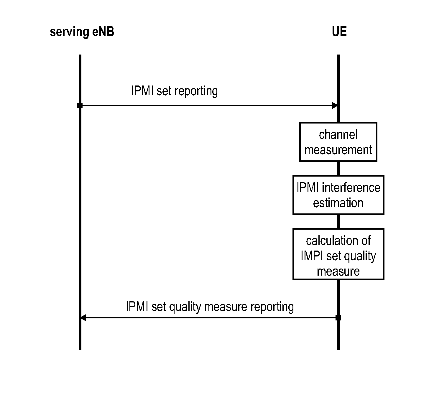
[0136]One aspect of the invention is to determine a more meaningful quality measure for a precoding matrix set that might be used by an inteferer base station in a neihbouring cell. It is assumed that the interfering base station applies an precoding matrix (IPMI) restriction...


PUM


Abstract

The invention relates to methods for determining the interference variability of a precoding matrix set, and the use of same for purposes of scheduling and precoding matrix set selection. The precoding matrix set used by an interferer base station is evaluated by the mobile terminal which experiences the intercell interference from the interferer base station. The mobile terminal is informed about the precoding matrices of the precoding matrix set used by the base station. The mobile terminal measures the radio channel to the interferer cell, and then estimates based on the measured radio channel and with the knowledge on the particular precoding matrices of the precoding matrix set, the interference variability of the precoding matrix set. The interference variability may be reported to the serving base station of the mobile terminal, and thus considered for scheduling decisions by the serving base station referring the mobile terminal.

Description

FIELD OF THE INVENTION[0001]The invention relates to methods for determining a quality measure of a precoding matrix set used by an interferer base station. The invention is also providing the mobile terminal and the base station apparatus for performing the methods described herein.TECHNICAL BACKGROUNDLong Term Evolution (LTE)[0002]Third-generation mobile systems (3G) based on WCDMA radio-access technology are being deployed on a broad scale all around the world. A first step in enhancing or evolving this technology entails introducing High-Speed Downlink Packet Access (HSDPA) and an enhanced uplink, also referred to as High Speed Uplink Packet Access (HSUPA), giving a radio-access technology that is highly competitive.[0003]In order to be prepared for further increasing user demands and to be competitive against new radio access technologies, 3GPP introduced a new mobile communication system which is called Long Term Evolution (LTE). LTE is designed to meet the carrier needs for h...

Claims


Application Information

Patent Timeline
Patent Type & Authority Applications(United States)
IPC IPC(8): H04B7/06H04B7/04H04B7/02
CPCH04B7/0639H04B7/024H04B7/0417H04B7/0665H04B7/0634H04B7/0654H04B7/0632
Inventor EINHAUS, MICHAELWENGERTER, CHRISTIANGOLITSCHEK EDLER VON ELBWART, ALEXANDERHOSHINO, MASAYUKI
Owner PANASONIC INTELLECTUAL PROPERTY CORP OF AMERICA
Why Eureka
Try Eureka