

Antenna system
- Summary
- Abstract
- Description
- Claims
- Application Information
AI Technical Summary
Benefits of technology
Problems solved by technology
Method used
Image

Examples
Embodiment Construction
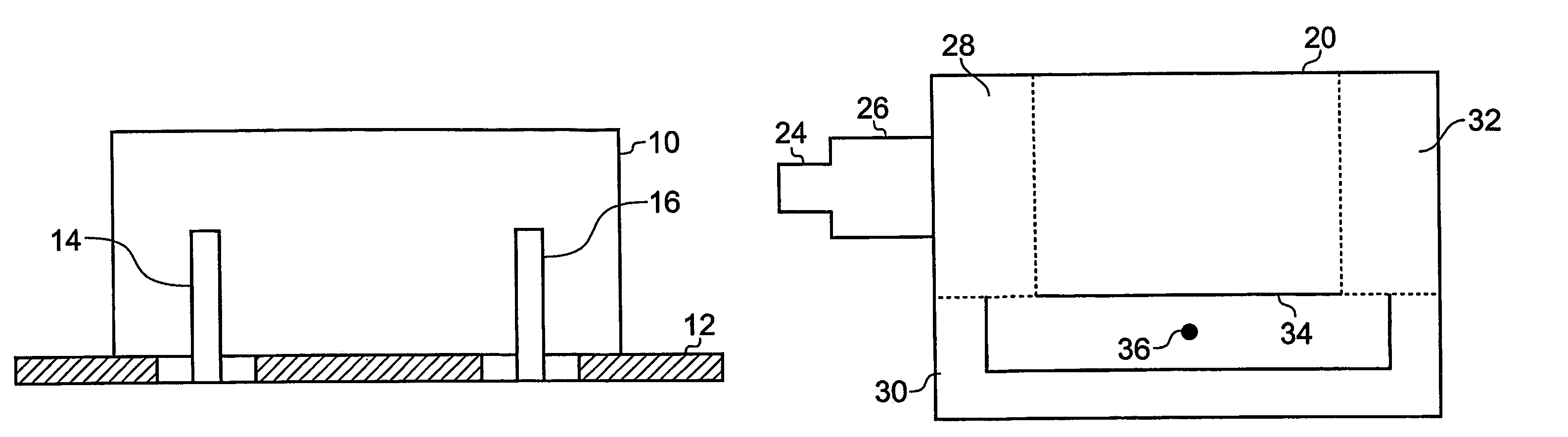
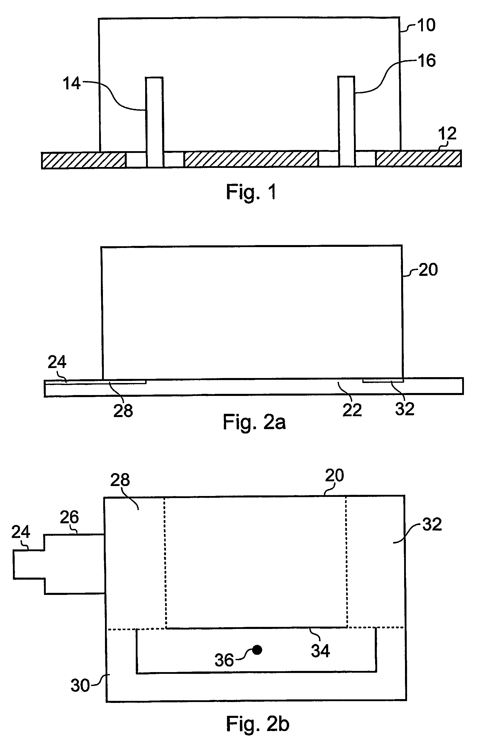
[0027]FIG. 1 is a schematic side view of an antenna system in accordance with the present invention. A “puck” of dielectric material 10 is sized and shaped to resonate, and therefore act as an antenna, in the desired operational frequency range, and is mounted on a ground plane 12.
[0028]The operational bandwidth of the antenna is determined by, amongst other things, the dielectric constant of the dielectric material, and the radius-to-height ratio of the puck (if the puck has a circular cross-section), and these parameters can be chosen in a conventional way to achieve the desired bandwidth in the system shown herein. In this illustrative preferred embodiment of the invention, the dielectric material is in the form of a cuboid, having length:height:width ratios of 2:1:0.8.
[0029]One conventional way of feeding an electrical signal to a dielectric resonator is by way of a monopole coaxial feed line. However, in the embodiment of the present invention shown in FIG. 1, there are two suc...
PUM
 Abstract
Description
Claims
Application Information