
Method and arrangement for the transmission of working signals and protection signals via optical data networks

a technology of optical data network and working signal, applied in multiplex communication, polarisation multiplex system, instruments, etc., can solve the problem of sharp reduction of transmission capacity, and achieve the effect of wide transmission bandwidth, high data rate, and low attenuation

Inactive Publication Date: 2007-03-22
XIEON NETWORKS SARL
View PDF5 Cites 3 Cited by
  • Summary
  • Abstract
  • Description
  • Claims
  • Application Information

AI Technical Summary

Benefits of technology

[0003] Today, because of their wide transmission bandwidth and their low attenuation, glass fibers are used for the transmission of digital signals with high data rates. To enable the transmission capacity of the glass fiber to be utilized, a number of signals featuring different wavelengths (WDM signals) are transmitted in parallel over a fiber. In this case a number of transmission channels are combined into bands. 2-fiber systems are mostly used in which the data signal is transmitted in one direction in each case. Single-fiber systems are however also known, with which different frequency bands or interleaved data signals with particular frequencies are transmitted in either direction. 4-fiber systems are also known for increasing the transmission capacity or for providing protection switching.
[0004] A ring structure shown in FIG. 1 is described in a contribution to the “22nd Conference on Optical Communication—ECOC 96, Oslo, WeB.2.3, 178 pages 3.51-3.54 “First results of an experimental Coloured Section Ring”, in which adjacent ADD / DROP multiplexers are connected to each other bidirectionally via two fibers in each case. For each transmission section between two adjacent DROP multiplexers only one wavelength is needed for both directions of transmission on each fiber. However different wavelengths are used on all transmission sections of the ring. The signals are added or dropped via optical ADD / DROP multiplexers which contain optical fibers. If for example a working connection is interrupted by a broken fiber, a protection connection is established via the (mostly) longer intact ring section using the same wavelength, i.e. the working signals previously sent over the interrupted section are “looped back” and transmitted over the intact sections. The advantage of this is that the wavelength does not need to be converted. Instead of for an individual wavelength this method can naturally also be employed for a number of wavelengths and transmission bands. Although the method offers the advantage that the wavelength for protection connections does not need to be converted, it does however sharply reduce the transmission capacity.
[0005] The object of the invention is to provide protection connections which do not have an adverse effect on transmission capacity.

Problems solved by technology

Although the method offers the advantage that the wavelength for protection connections does not need to be converted, it does however sharply reduce the transmission capacity.

Method used


Image

  • Method and arrangement for the transmission of working signals and protection signals via optical data networks
  • Method and arrangement for the transmission of working signals and protection signals via optical data networks
  • Method and arrangement for the transmission of working signals and protection signals via optical data networks

Examples


Embodiment Construction

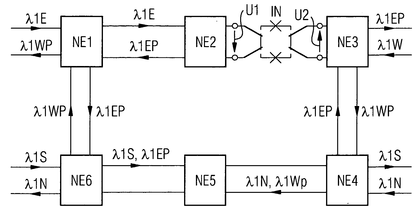
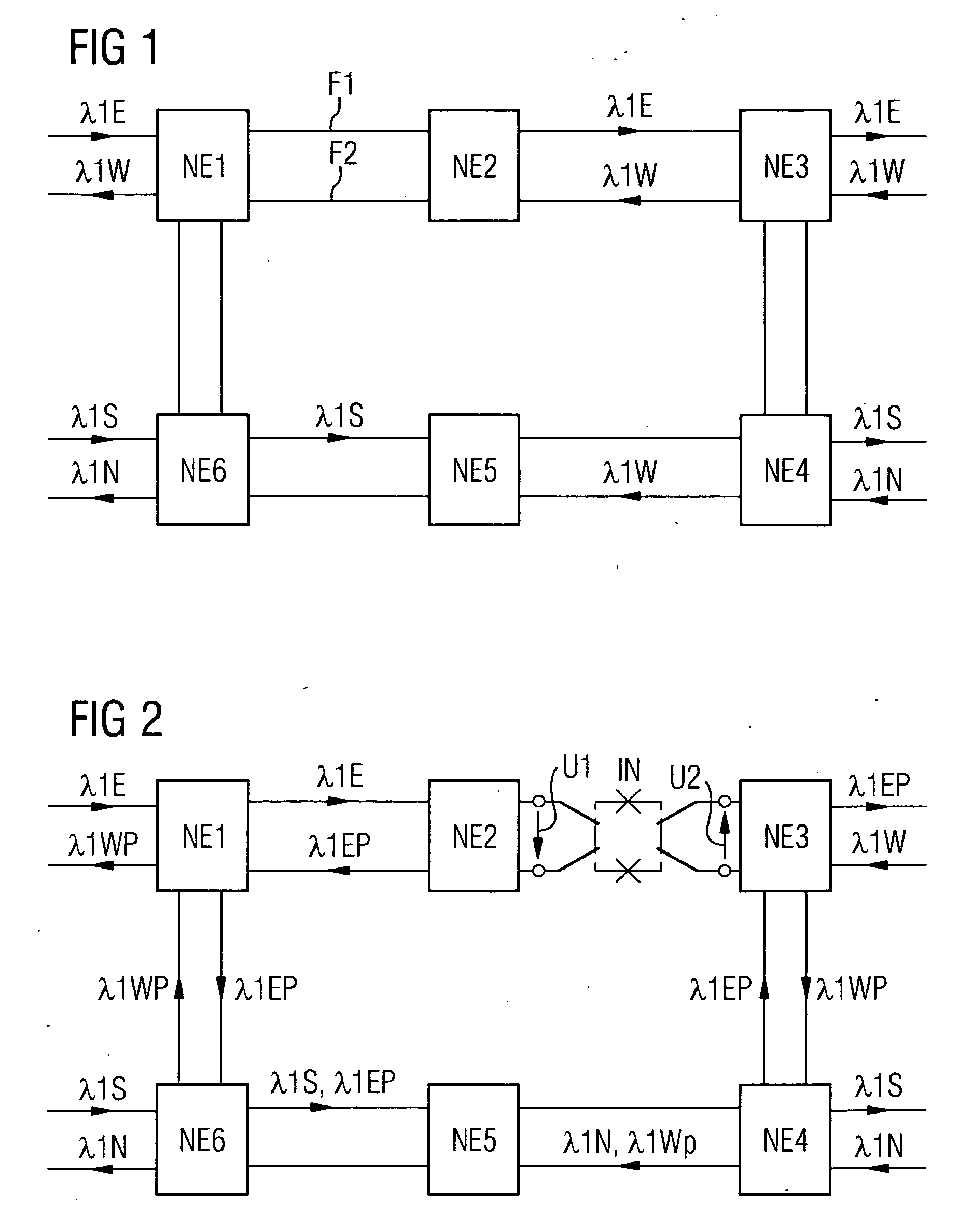
[0017]FIG. 1 shows an extended 2-fiber ring network structure. A ring network formed with two fibers F1 and F2 features the network elements NE1 to NE6. For a connection (channel) between the network element NE1 and the network element NE3 a wavelength λ1 is used, with a working signal λ1E being transmitted in an easterly direction over the first fiber F1 and a working signal λ1W with the same wavelength being transmitted in the opposite direction. The same wavelength can also be used for transmission for example between the network elements in NE4 and NE6. The corresponding signals are labeled λ1S and λ1N. Naturally there will generally be more channels with other wavelengths present for connecting the other network elements, but these can be left out of our considerations for the purposes of explaining the invention.

[0018]FIG. 2 shows a fiber break at an interruption point between the network elements. The connection path NE1-NE2-NE3 is interrupted. In the known way the send sign...


PUM


Abstract

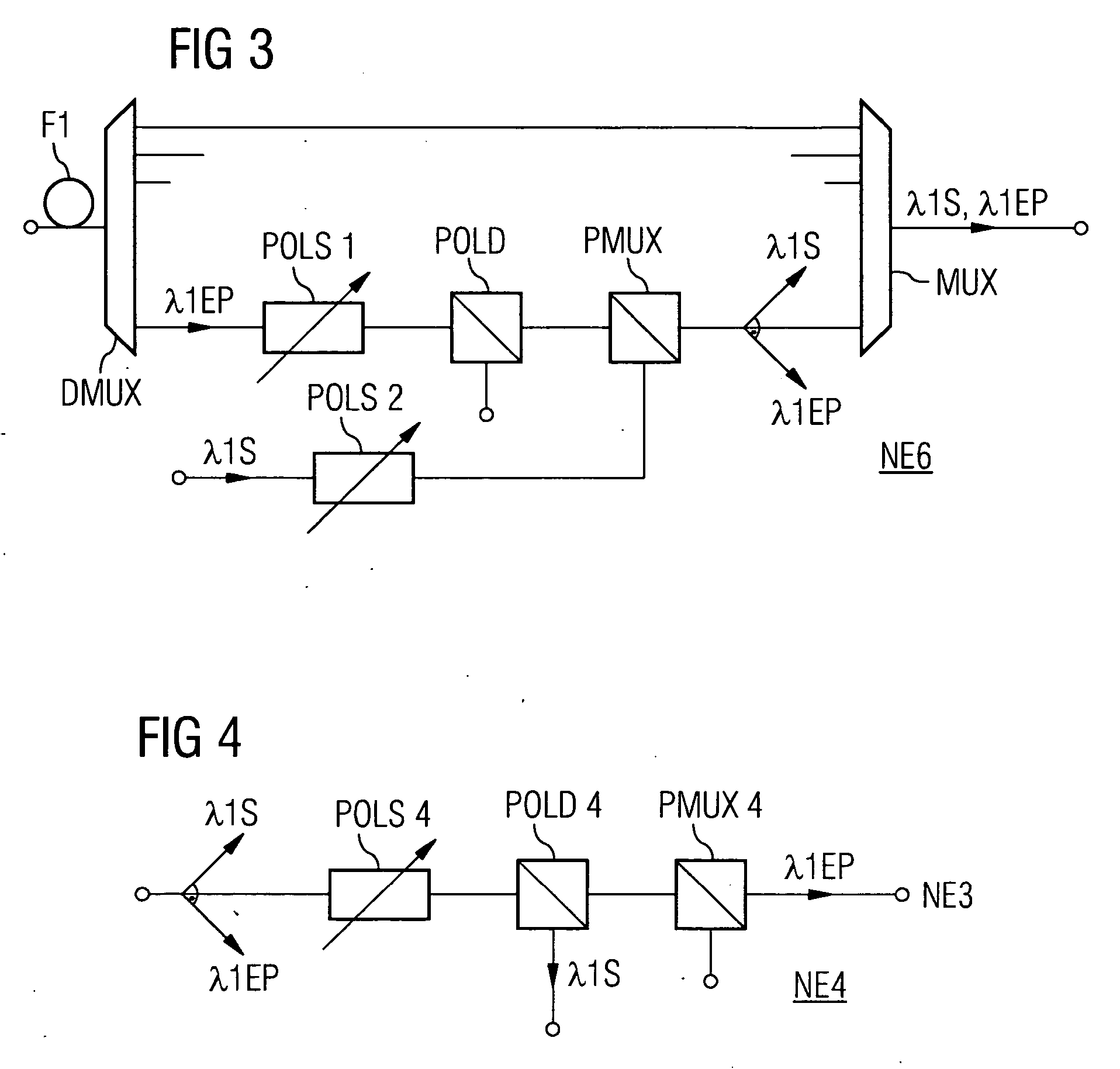
According to the invention, working signals are transmitted between network elements via a first communication path. The protection signals are transmitted continuously or in case of a fault at the same wavelength as the working signals via a second communication path of an optical network while the polarization of the protection signals is adjusted orthogonal to the polarization of additional working signals which are transmitted at the same wavelength via sections of the second communication path such that no wavelengths need to be kept clear for protection signals.

Description

CROSS REFERENCE TO RELATED APPLICATIONS [0001] This application is the US National Stage of International Application No. PCT / EP2004 / 000573, filed Jan. 23, 2004 and claims the benefit thereof. The International Application claims the benefits of German application No. 10308306.5, filed Feb. 26, 2003, both applications are incorporated by reference herein in their entirety.FIELD OF INVENTION [0002] The invention relates to method and an arrangement for the transmission of working signals and protection signals via optical data networks. SUMMARY OF THE INVENTION [0003] Today, because of their wide transmission bandwidth and their low attenuation, glass fibers are used for the transmission of digital signals with high data rates. To enable the transmission capacity of the glass fiber to be utilized, a number of signals featuring different wavelengths (WDM signals) are transmitted in parallel over a fiber. In this case a number of transmission channels are combined into bands. 2-fiber s...

Claims


Application Information

Patent Timeline
Patent Type & Authority Applications(United States)
IPC IPC(8): H04B10/00H04J14/06
CPCH04J14/0283H04J14/0291H04J14/06H04J14/0295H04J14/0294
Inventor HECKER, NANCYRICHTER, ALEXANDERSABIDO PONCE, CARLOS ENRIQUE
Owner XIEON NETWORKS SARL
Learn More