Exercise weight plate with integral retaining mechanism.
- Summary
- Abstract
- Description
- Claims
- Application Information
AI Technical Summary
Benefits of technology
Problems solved by technology
Method used
Image

Examples
Embodiment Construction
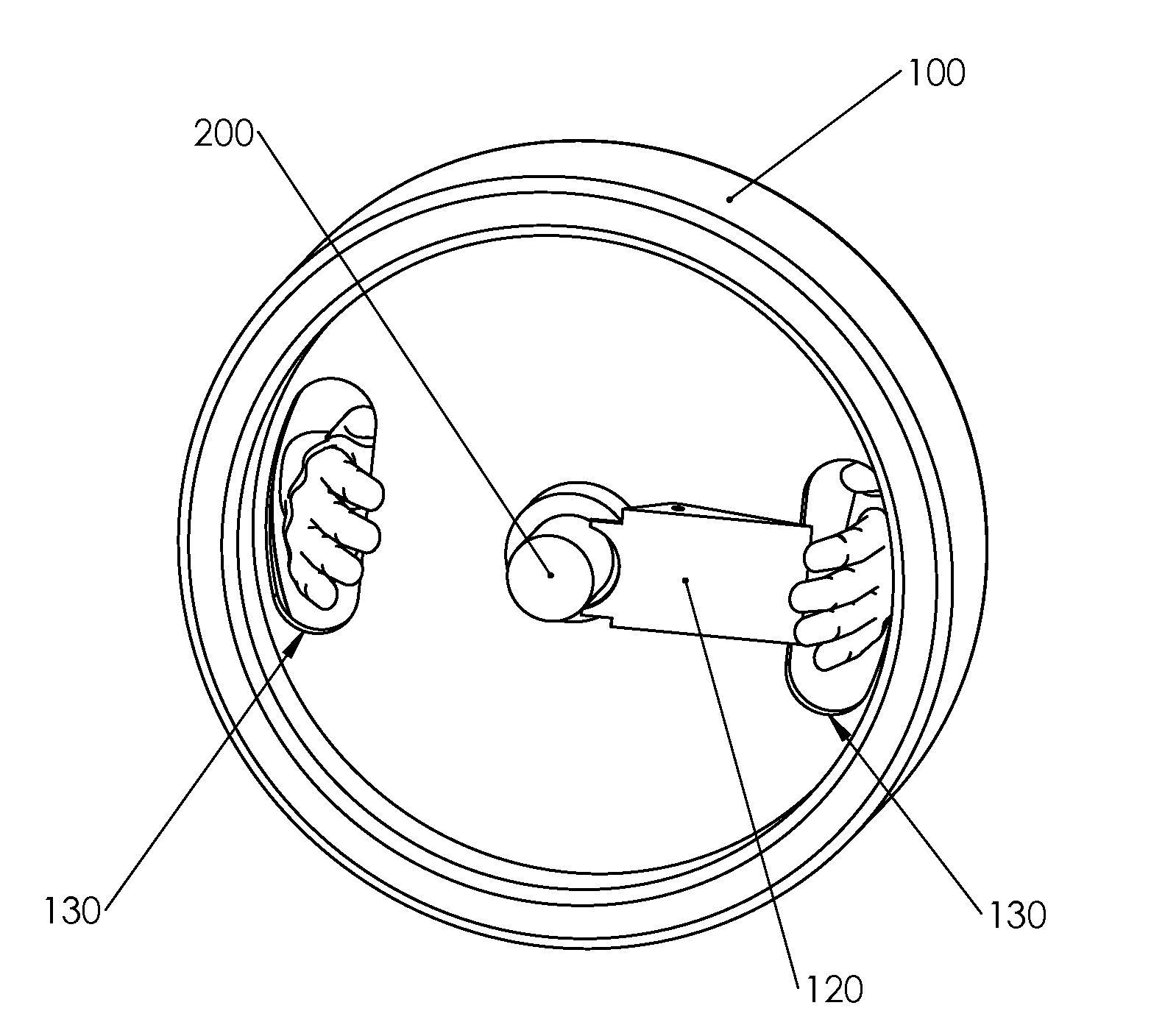
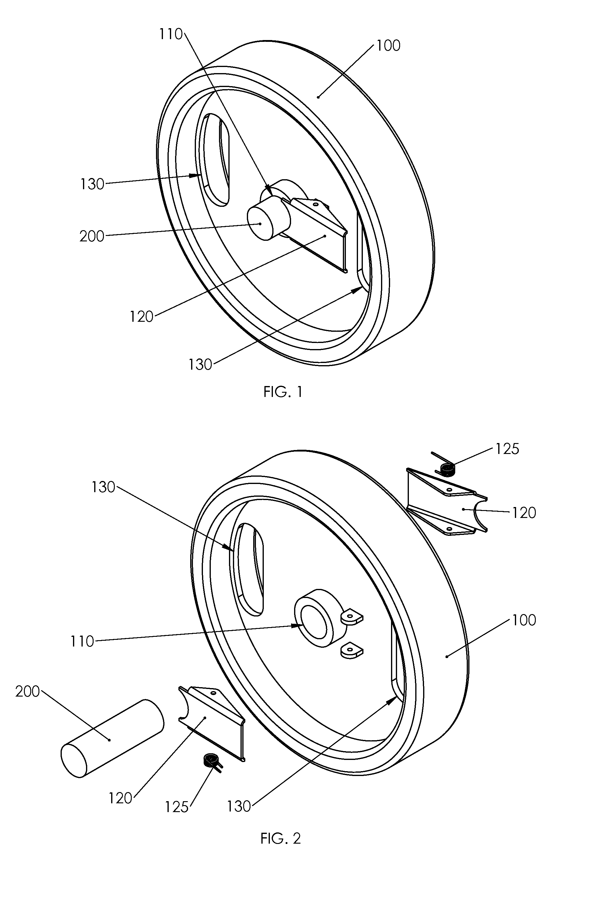
[0016]An embodiment of the present invention is shown in FIG. 1. The weight plate 100 engages slidingly with cylindrical bar 200 by means of bore 110. In the illustrated embodiment, two retaining means 120, in the form of simple clamps, are urged into clamping position by springs 125 which are shown in the exploded view FIG. 2. Apertures 130 are provided in order that the user may grasp the weight plate assembly for easy handling, as illustrated in FIG. 5.
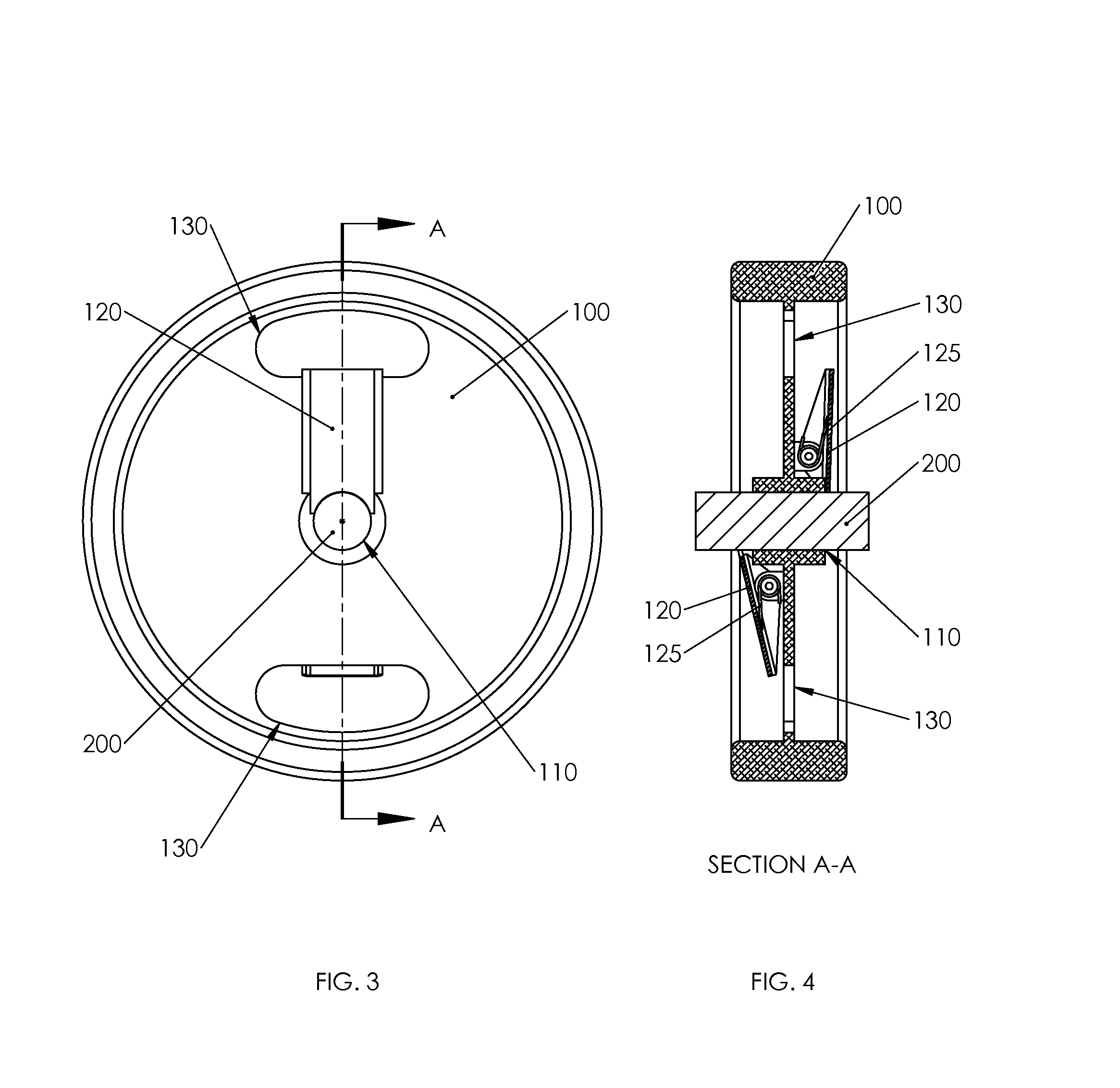
[0017]FIG. 3 shows a front view of the weight plate of the present invention and FIG. 4 is a corresponding side cross-sectional view. In FIG. 4 one clamp 120 is shown engaged which is the default position into which the clamp is urged by spring 125, and a second clamp 120 is shown disengaged, as it would be if actuated by the user during installation or removal.
[0018]In the illustrated embodiment, each clamp 120, when engaged, substantially prevents movement of the weight plate 100 relative to cylindrical bar 200 in one axial direc...
PUM
 Abstract
Description
Claims
Application Information