Wireless power repeater

a repeater and wireless technology, applied in the direction of transformers, transmission, inductances, etc., can solve the problems of inconvenient user look, connection failure, and degraded exterior appearance, so as to increase the efficiency of power transmission and increase the efficiency of wireless power

Active Publication Date: 2014-10-02
SCRAMOGE TECH LTD
View PDF9 Cites 41 Cited by
  • Summary
  • Abstract
  • Description
  • Claims
  • Application Information

AI Technical Summary

Benefits of technology

The invention allows for more efficient use of electrical energy by allowing multiple types of electricity (electric current) charges on an electronics device without affecting their position relative to each other. This means that they may work better with different configurations of wires used within them while still being able to efficiently transfer data wirelessly over longer distances than traditional methods like cables.

Problems solved by technology

The technical problem addressed in this patent text is the inconvenience and safety issues caused by the use of wired and contact-type chargers for portable electronic devices, as well as the inefficiency and limitations of wireless charging schemes based on the size and capacity of the target device. The patent aims to provide a solution to these issues by developing a charging system that can adapt to various electronic devices and simultaneously charge multiple devices with different shapes and sizes.

Method used


Image

  • Wireless power repeater
  • Wireless power repeater
  • Wireless power repeater

Examples


Embodiment Construction

[0024]Hereinafter, embodiments will be described in detail with reference to accompanying drawings so that those skilled in the art can easily work with the embodiments.

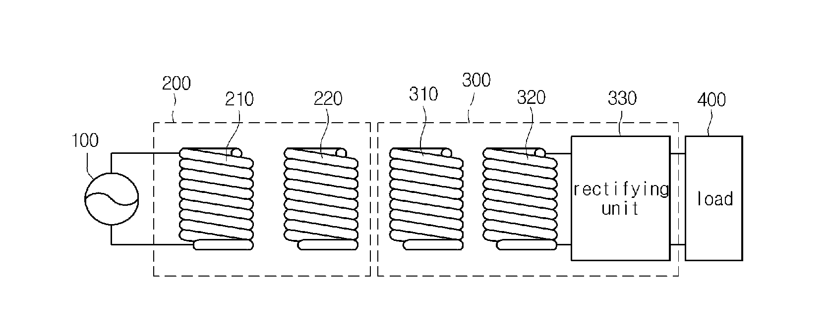
[0025]FIG. 1 is a view showing a wireless power transmission system according to one embodiment of the disclosure.

[0026]Referring to FIG. 1, the wireless power transmission system may include a power supply apparatus 100, a wireless power transmitter 300, a wireless power receiver 300, and a load 400.

[0027]According to one embodiment, the power supply apparatus 100 may be included in the wireless power transmitter 200.

[0028]The wireless power transmitter 200 may include a transmission induction coil 210 and a transmission resonant coil 220.

[0029]The wireless power receiver 300 may include a reception resonant coil, a reception induction coil 320, a rectifying unit 330, and the load 400.

[0030]Both terminals of the power supply apparatus 100 are connected to both terminals of the transmission induction coil 210.

[0031]T...


PUM


Abstract

Disclosed is a wireless power repeater. The wireless power repeater repeats power between a wireless power transmitter and an electronic device. The wireless power repeater includes a charging container having at least one side, wherein the charging container has a form for receiving the electronic device, a repeating coil placed at one of the at least one side of the charging container to repeat the power between the wireless power transmitter and the electronic device using resonance.

Description


Claims


Application Information

Patent Timeline
Owner SCRAMOGE TECH LTD
Why Eureka
Try Eureka