Rapid Deployment Lighting System

a lighting system and rapid technology, applied in the field of rapid deployment lighting systems, can solve the problems of cumbersome logistical supply chain, time-consuming generator setup, undesired delay in tent deployment,

Active Publication Date: 2014-10-02
HOPPER MICHAEL BLAIR
View PDF5 Cites 18 Cited by
  • Summary
  • Abstract
  • Description
  • Claims
  • Application Information

AI Technical Summary

Benefits of technology

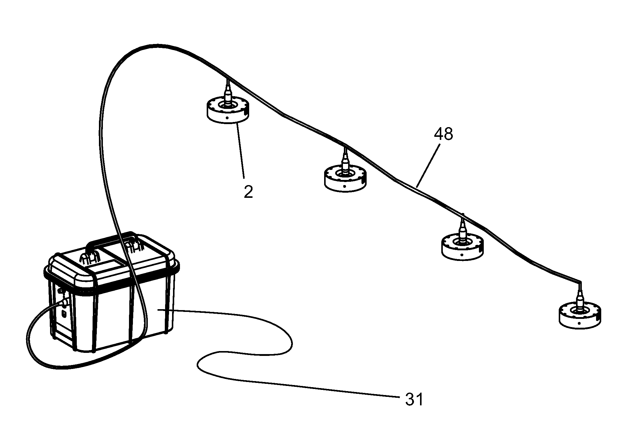
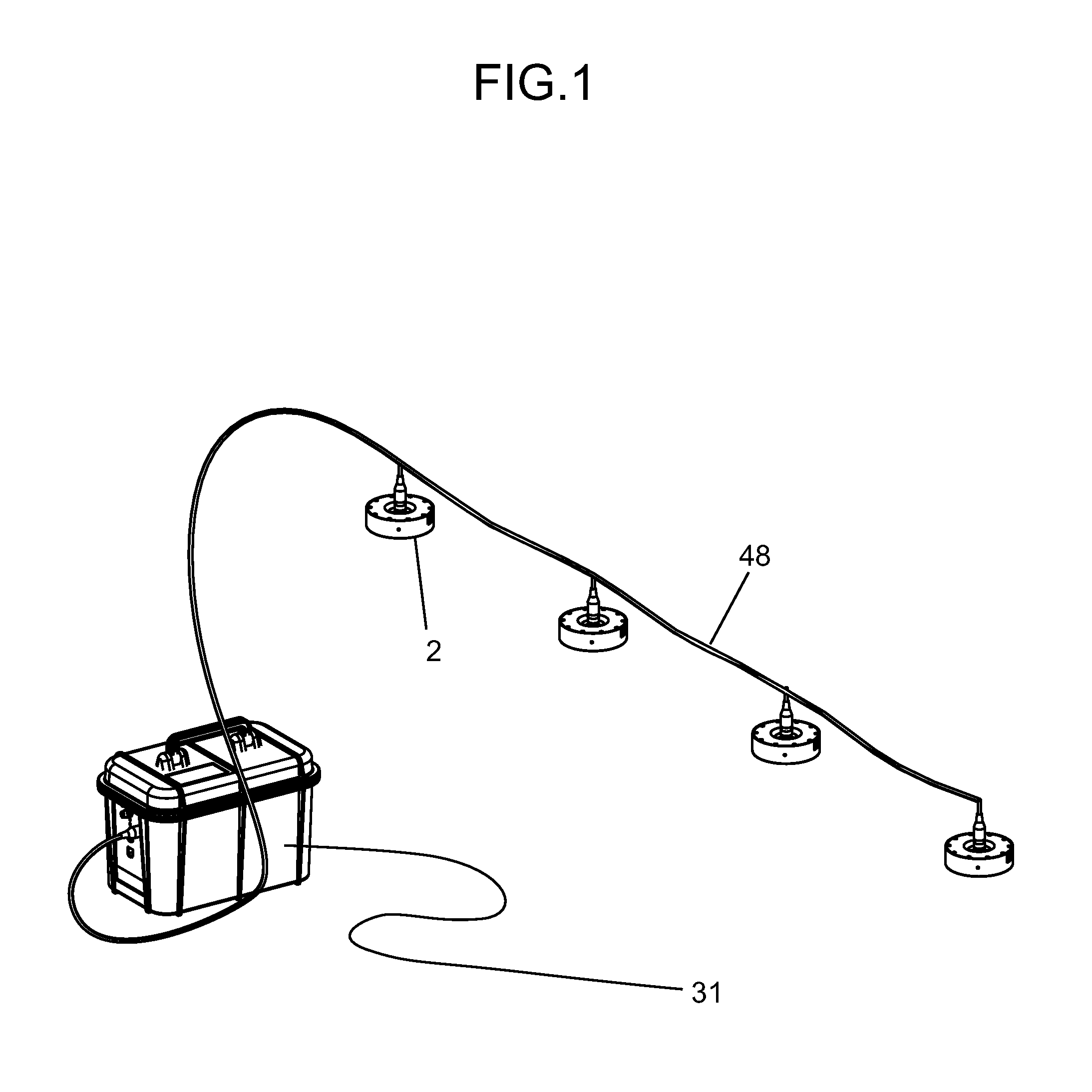
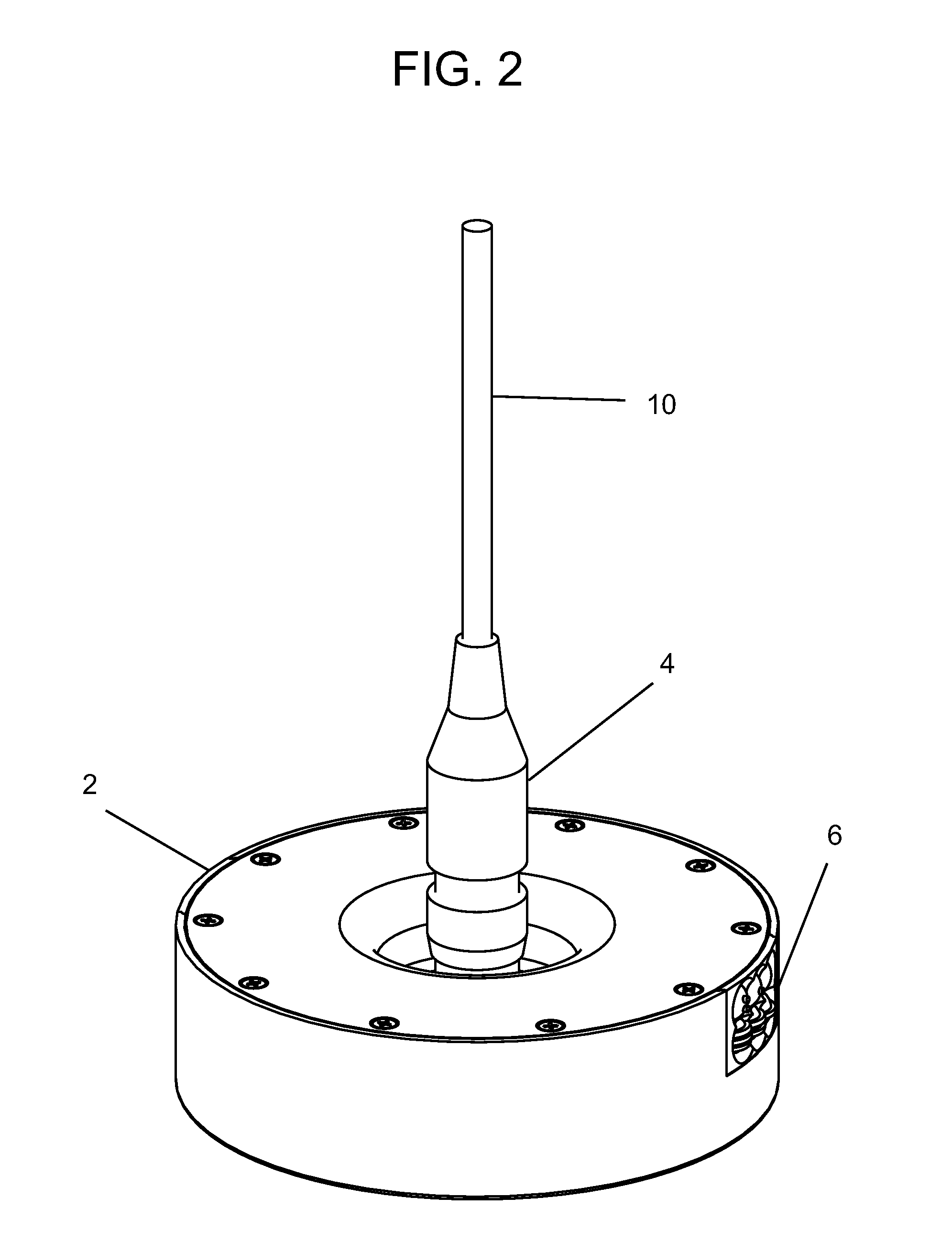
[0007]According to one aspect of the invention, a rapidly deployable portable lighting system includes a low voltage rechargeable power source, and a plurality of lights, each including a housing, a plurality of LEDs disposed in spaced relation within the housing and configured to receive operational power from the low voltage rechargeable power source, the LEDs configured to selectively transmit light of at least two mutually distinct colors within a field of illumination, and a power port including a first quick-release connector portion. The system also includes a wiring harness having a first end portion configured for being communicably coupled to the power source, and a second end portion having a plurality of second quick-release connector portions disposed in spaced relation thereon. The second quick-release connector portions are configured for quick-release engagement with the first quick-release connector portions to supply power from the power source to the lights. A controller is configured to selectively switch individual LEDs on and off, independently of one another, to control illumination within the field of illumination. A smart case includes the power source and controller integrally disposed therein, and is sized and shaped to receive the lights and wiring harness therein for storage and transport. The lights and wiring harness may be removed from the case for deployment, wherein the first end portion is communicably coupled to the power source and the second end portion is extended to the lights disposed in spaced relation within a tent or other area to be illuminated.

Problems solved by technology

Generator setup is time consuming and often serves to undesirably delay tent deployments.
Generators also have many requirements, including fuel, maintenance, trained personnel for operation and maintenance, and a cumbersome logistical supply chain including various personnel to move them to their intended deployment destinations.
Currently, when a generator runs out of fuel or has a mechanical malfunction, all the lights connected to it go out.
Generators also create diesel fumes and noise that may give away positions and potentially put missions at risk.
Generators used in combat locations also present ‘secondary explosion’ risk which often require placement underground.
In addition, the conventional light bulbs used in these systems tend to be relatively energy inefficient, fragile, and burn out relatively frequently.
It is also noted that when a mission changes status, e.g., to a ‘red alert’ status, white bulbs in current lighting systems need to be quickly unscrewed and replaced with red bulbs, which is relatively labor intensive and often results in burned fingers.
It is also noted that the average conventional light kit for a U.S. Army “GP medium tent” (16 ft.×32 ft.) weighs about 320 pounds, is bulky, and uses threaded connectors that may be easily cross threaded and rendered inoperable, particularly when setup is completed in the dark.

Method used


Image

  • Rapid Deployment Lighting System
  • Rapid Deployment Lighting System
  • Rapid Deployment Lighting System

Examples


Embodiment Construction

[0023]In the following detailed description, reference is made to the accompanying drawings that form a part hereof, and in which is shown by way of illustration, specific embodiments in which the invention may be practiced. These embodiments are described in sufficient detail to enable those skilled in the art to practice the invention, and it is to be understood that other embodiments may be utilized. It is also to be understood that structural, procedural and system changes may be made without departing from the spirit and scope of the present invention. In addition, well-known structures, circuits and techniques have not been shown in detail in order not to obscure the understanding of this description. The following detailed description is, therefore, not to be taken in a limiting sense, and the scope of the present invention is defined by the appended claims and their equivalents.

[0024]As used herein, the terms “computer” and “end-user device” are meant to encompass a workstat...


PUM


Abstract

A rapidly deployable portable lighting system includes a low voltage rechargeable power source, lights, and a wiring harness configured for being coupled to the lights with quick-release connectors. Each light includes a housing, LEDs receiving power from the power source and transmitting light of at least two colors, and a power port for connecting to the wiring harness. A controller is configured to selectively switch individual LEDs on and off, independently of one another, to control illumination. A smart case houses the power source and controller integrally therein, and is sized and shaped to receive the lights and wiring harness for storage and transport. The lights and wiring harness may be removed from the case for deployment.

Description

RELATED APPLICATION[0001]This application claims the benefit of U.S. Provisional Patent Application Ser. No. 61 / 704,114, entitled RDLS Rapid Deployment Lighting System, filed on Sep. 21, 2012, the contents of which are incorporated herein by reference in their entirety for all purposes.TECHNICAL FIELD[0002]This invention relates to lighting systems, and more particularly to a portable, self-contained, and energy efficient system configured for being rapid deployment.BACKGROUND INFORMATION[0003]Throughout this application, various publications, patents and published patent applications are referred to by an identifying citation. The disclosures of the publications, patents and published patent applications referenced in this application are hereby incorporated by reference into the present disclosure.[0004]There is a need to have a lighting system for military tent deployments that can be setup quickly without the need for generators and their associated shock hazards. Current milita...

Claims


Application Information

Patent Timeline
Patent Type & Authority Applications(United States)
IPC IPC(8): F21L4/02F21L4/08H05B44/00
CPCF21L4/08F21L4/02F21S2/00F21S9/02F21V23/001F21V23/008F21V23/023F21V23/0435F21S9/032F21V17/007F21S4/10F21Y2115/10F21Y2113/13F21L14/00H05B45/00H05B47/175Y02B20/40H05B45/325
Inventor HOPPER, MICHAEL BLAIR
Owner HOPPER MICHAEL BLAIR
Why Eureka
Try Eureka