
Actively Controllable Stent, Stent Graft, Heart Valve and Method of Controlling Same

Active Publication Date: 2014-10-02
EDWARDS LIFESCI CARDIAQ
View PDF4 Cites 329 Cited by
  • Summary
  • Abstract
  • Description
  • Claims
  • Application Information

AI Technical Summary

Benefits of technology

The patent describes a new type of prosthesis for repairing damaged blood vessels. These prosthesis have a unique design that allows them to adapt to the shape of the blood vessel they are replacing. They also have a mechanism that allows for remote adjustment and locking after deployment. This design allows for better accommodation of the local anatomy and may also allow for repositioning and resealing of the prosthesis after initial deployment.

Problems solved by technology

While some post-implantation remodeling of the aortic neck proximal to an endovascular graft (endograft) has been reported, existing endograft technology does not allow for the management of this condition without placement of an additional endograft sleeve to cover the remodeled segment.

Method used


Image

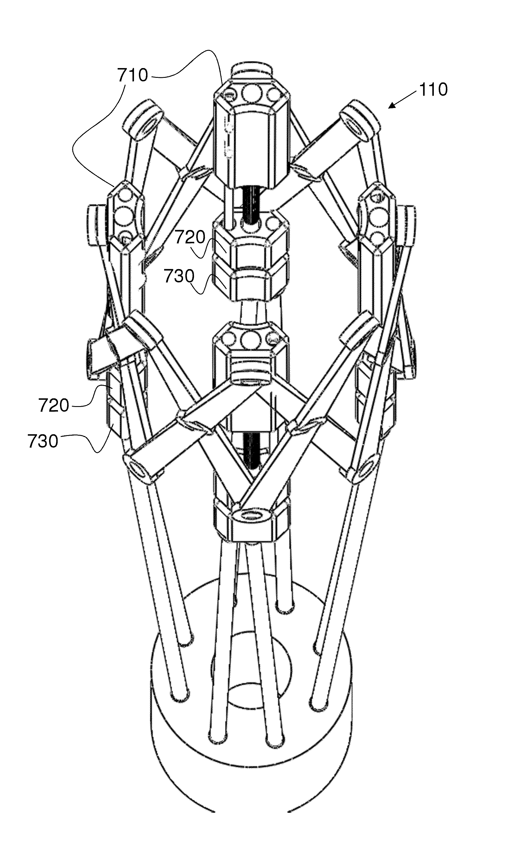
  • Actively Controllable Stent, Stent Graft, Heart Valve and Method of Controlling Same
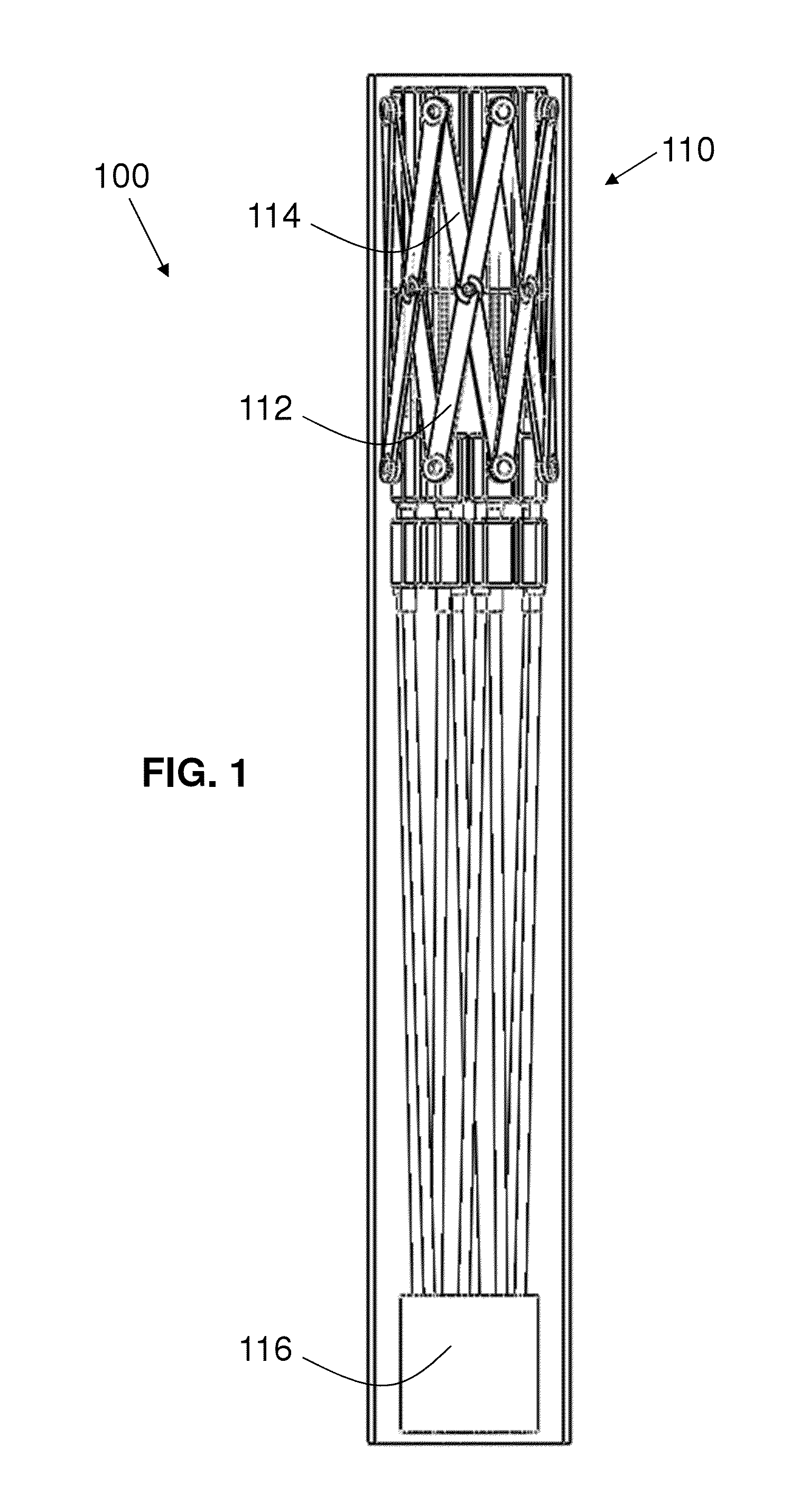
  • Actively Controllable Stent, Stent Graft, Heart Valve and Method of Controlling Same
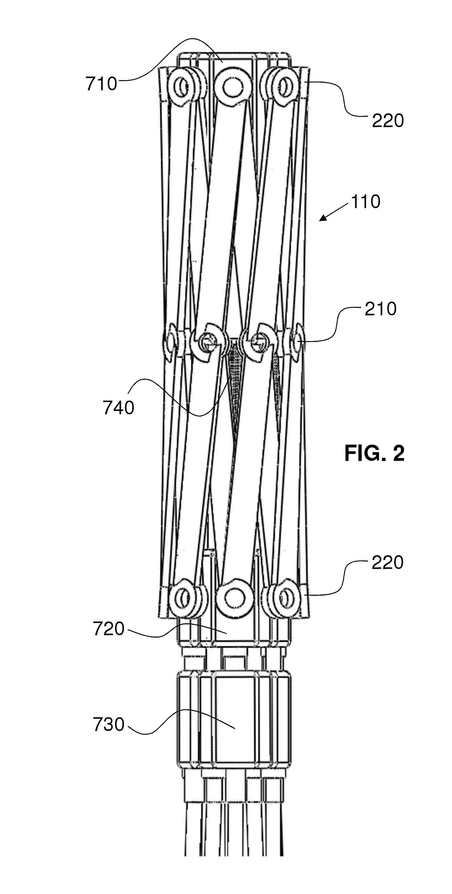
  • Actively Controllable Stent, Stent Graft, Heart Valve and Method of Controlling Same

Examples


Embodiment Construction

[0314]As required, detailed embodiments of the present invention are disclosed herein; however, it is to be understood that the disclosed embodiments are merely exemplary of the invention, which can be embodied in various forms. Therefore, specific structural and functional details disclosed herein are not to be interpreted as limiting, but merely as a basis for the claims and as a representative basis for teaching one skilled in the art to variously employ the present invention in virtually any appropriately detailed structure. Further, the terms and phrases used herein are not intended to be limiting; but rather, to provide an understandable description of the invention. While the specification concludes with claims defining the features of the invention that are regarded as novel, it is believed that the invention will be better understood from a consideration of the following description in conjunction with the drawing figures, in which like reference numerals are carried forwar...


PUM


Abstract

A method for implanting a stent includes contracting a self-expanding / forcibly-expanding stent of a shape-memory material set to a given shape to a reduced implantation size with a delivery system having drive wires. The stent has a selectively adjustable assembly with adjustable elements operatively connected to the drive wires such that, when the adjustable elements are adjusted by the drive wires, a configuration change in at least a portion of the self-expanding stent occurs. The contracted stent is inserted into a native annulus in which the stent is to be implanted. The drive wires are rotated with the delivery system to forcibly expand the stent into the native annulus. While rotating the drive wires, a torque applied to the drive wires is determined with the delivery system. Rotation of the drive wires is stopped based upon a value of the determined torque.

Description

CROSS-REFERENCE TO RELATED APPLICATIONS[0001]This application:[0002]claims the priority, under 35 U.S.C. §119, of copending U.S. Provisional Patent Application No. 61 / 824,264, filed May 16, 2013;[0003]is a continuation-in-part of U.S. patent application Ser. No. 11 / 888,009, filed Jul. 31, 2007, now U.S. Pat. No. 8,252,036, issued Aug. 28, 2012 (which application claims priority to U.S. Provisional Patent Application Nos. 60 / 834,401 and 60 / 834,627, filed Jul. 31, 2006, and Aug. 1, 2006, respectively);[0004]is a continuation-in-part of co-pending U.S. patent application Ser. No. 12 / 822,291, filed Jun. 24, 2010 (which application claims priority to U.S. Provisional Patent Application No. 61 / 222,646, filed Jul. 2, 2009);[0005]is a continuation-in-part of co-pending U.S. patent application Ser. No. 13 / 339,236, filed Dec. 28, 2011 (which application claims the priority to U.S. Provisional Patent Application No. 61 / 428,114, filed Dec. 29, 2010);[0006]is a continuation-in-part of U.S. paten...

Claims


Application Information

Patent Timeline
IPC IPC(8): A61F2/966
CPCA61F2/966A61F2250/0069A61F2/856A61F2/90A61F2/94A61F2/95A61F2002/067A61F2002/075A61F2002/077A61F2002/9511A61F2002/9534A61F2250/0018A61F2250/0039A61F2250/006A61F2250/0065A61F2/07A61F2/2412A61F2/2439A61F2/844A61F2002/9505A61F2250/0007A61B5/6862A61B5/021A61B5/026A61F2/2418A61F2/243A61F2/2436A61F2002/9665A61F2220/0041A61F2220/0075A61F2220/0091A61F2250/0006A61F2250/001A61F2/9517A61F2/2427
Inventor CARTLEDGE, RICHARDSMITH, KEVIN W.BALES, JR., THOMAS O.DEVILLE, DEREK DEEKLINE, KOREYMENDEZ, MAX PIERREPALMER, MATTHEW A.KIRK, MICHAEL WALTERRIVERA, CARLOSPETERSEN, ERICMCBRAYER, SEAN
Owner EDWARDS LIFESCI CARDIAQ
Learn More