
Personal Magnetic Surgical Instrument System

a surgical instrument and personal technology, applied in the field of unique personal magnetic surgical instrument system, can solve the problems of inability to remove an instrument from the depth of a pouch blindly or safely, and the accessibility of these instruments is often out of the immediate reach of the operator,

Inactive Publication Date: 2014-10-09
BRADEAUX
View PDF47 Cites 21 Cited by
  • Summary
  • Abstract
  • Description
  • Claims
  • Application Information

AI Technical Summary

Benefits of technology

The patent is about a device that allows medical instruments to be attached to a person's surgical gown in an operating setting. The device includes a pad that attaches to the gown and a magnet attached to the pad. The medical instruments are attached to the magnet, so that an operator can use them easily during surgery. The technical benefit of this device is to provide a convenient and efficient way for medical instruments to be easily attached to a surgical gown and used by an operator.

Problems solved by technology

Accessibility to these instruments however, is dependent on multiple factors that are often out of the control of the individual in need of them (referred to here as the “operator”—which may be the surgeon, resident, physician assistant, or any other person participating in the procedure).
Unfortunately, all of these are suboptimal solutions to the operator's needs.
However, the instruments are frequently out of the immediate reach of the operator and still are typically passed from the instrument assistant to the operator when they are needed.
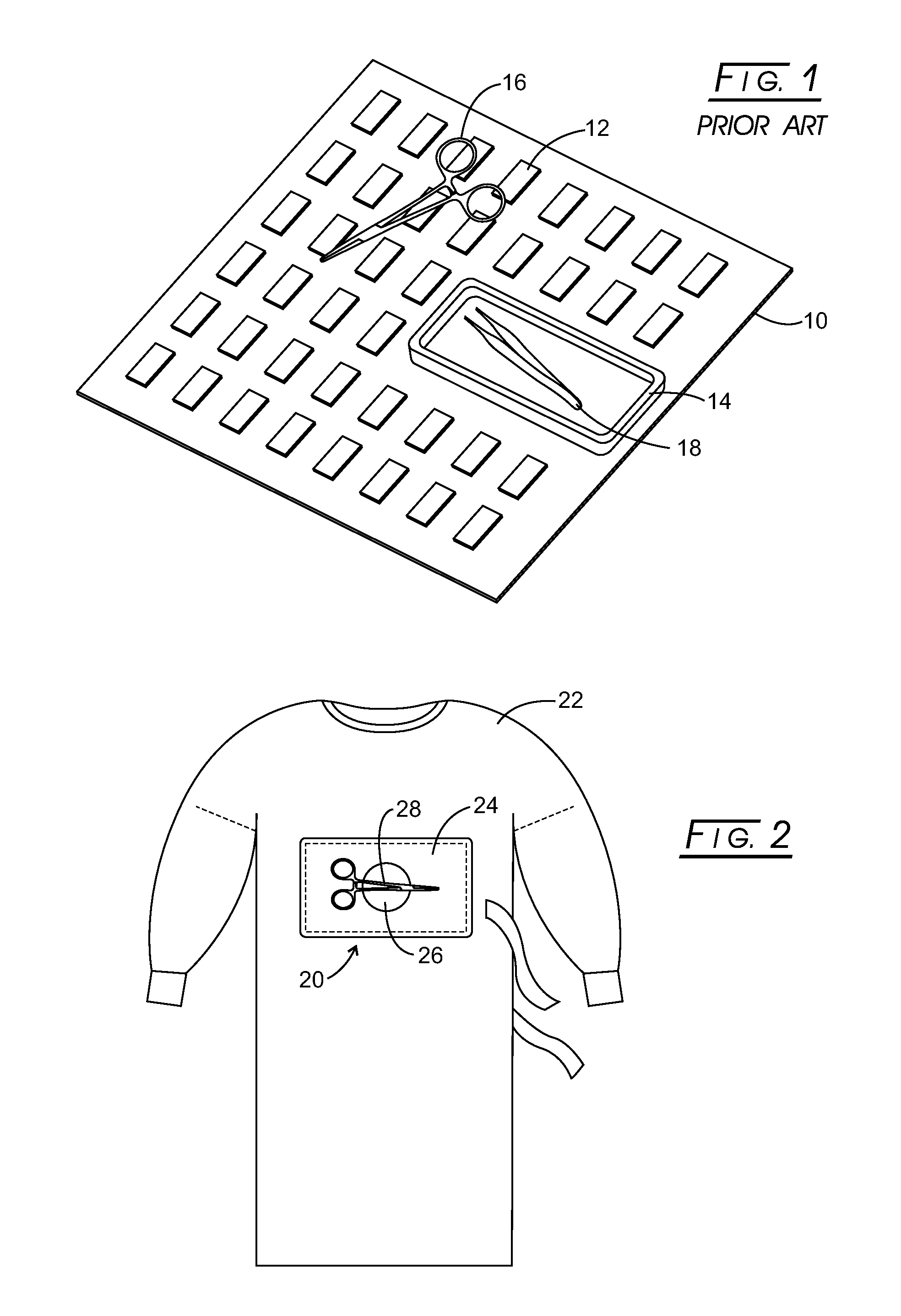
The limitations of the surgical instrument storage pack in U.S. Pat. No. 6,308,875, which seeks to make instruments available in a pouch adhered to the operators gown, include that removal of an instrument from the depth of a pouch cannot always be done blindly or safely.
The position of an instrument within the pouch also is not fixed, especially when more than one instrument is inside.
Such a device clearly would not translate into the surgical setting due to the inherent multiple risks associated with arm mobility (e.g., poor visibility of objects at all times, easily dislodged items, injury to oneself or others, adherence of unwanted objects or instruments, risk of misplacing small items within the patient, etc.

Method used


Image

  • Personal Magnetic Surgical Instrument System
  • Personal Magnetic Surgical Instrument System
  • Personal Magnetic Surgical Instrument System

Examples


Embodiment Construction

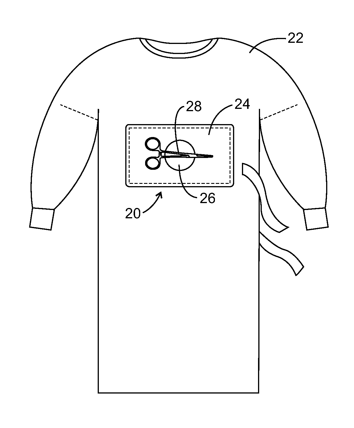
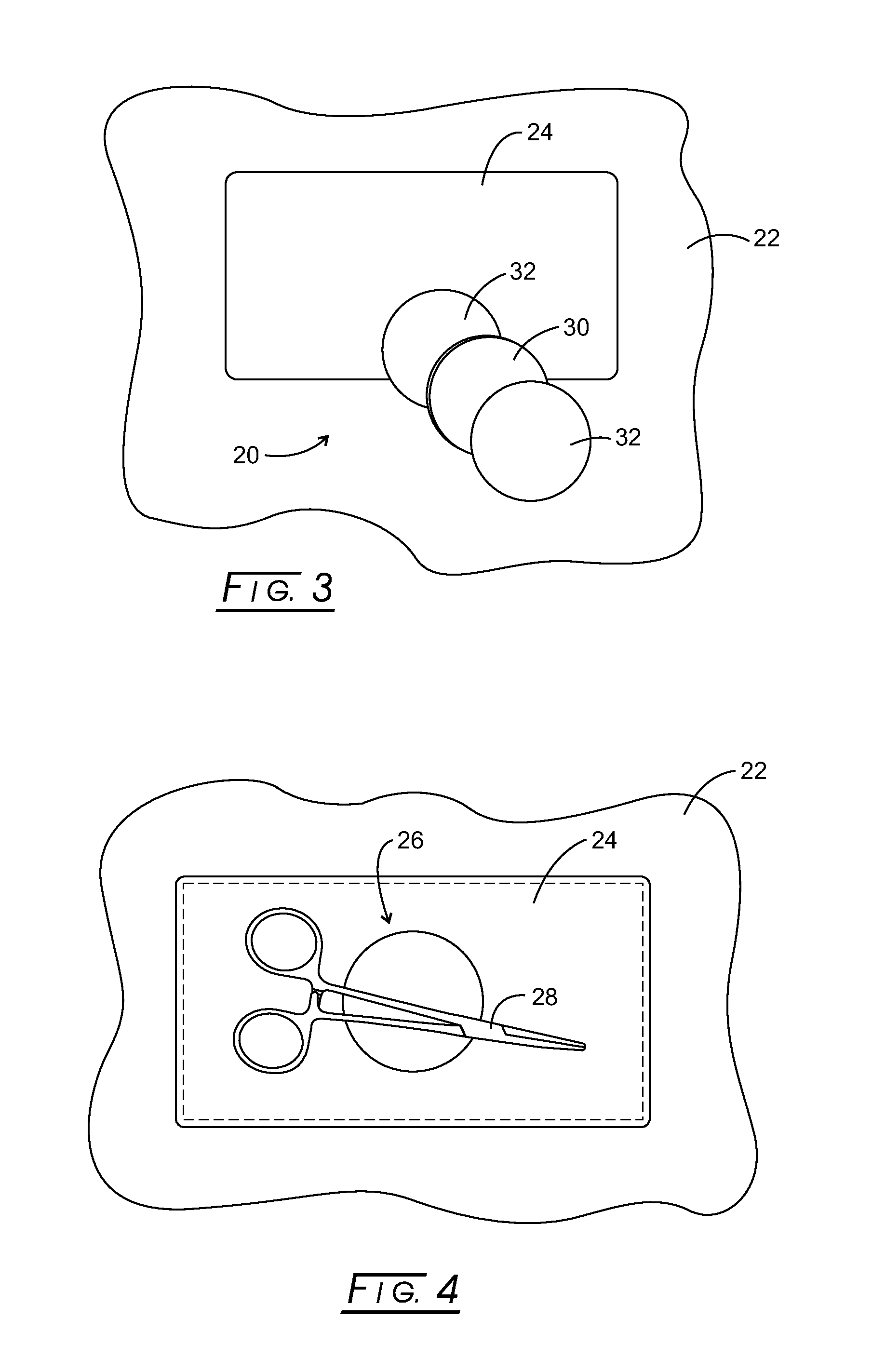
[0033]The disclosed personal magnetic surgical instrument system is a novel surgical instrument device designed to increase the autonomy of the operator by allowing for safe, immediate, and repetitive access to surgical instrumentation. It is comprised of an optional tactile landing zone material, ideally situated somewhere between the abdomen and the chest of the user or operator with a centrally located magnet(s) upon which a surgical instrument can be temporarily placed.

[0034]An additional benefit of the disclosed system is the reduction of misplaced or lost instruments. Also, the need for immediate access to instruments in emergencies or when time is critical to the health of the patient. The landing pad may be omitted in some versions of the disclosed personal magnetic surgical instrument system, as well as the use of multiple landing pads.

[0035]A variety of (preferably, non-sharp) common instruments for use with the disclosed personal magnetic surgical instrument system typica...


PUM

PropertyMeasurementUnit
polymericaaaaaaaaaa
depthaaaaaaaaaa
flexibleaaaaaaaaaa

Abstract

Disclosed is a device to which medical instruments may be removably attached in an operating theater. Such device includes a landing pad attachable to a surgical gown about the region between the abdomen and chest of a person wearing the surgical gown and a magnet attached to the landing pad. Medical instruments are removably attached to the magnet for use by an operator in a surgical theater.

Description

CROSS-REFERENCE TO RELATED APPLICATIONS[0001]This application claims benefit of provisional application Ser. No. 61 / 809,459 filed Apr. 8, 2013.STATEMENT REGARDING FEDERALLY SPONSORED RESEARCH[0002]Not applicable.BACKGROUND[0003]The present disclosure relates generally to accessing certain medical instruments during the course of surgery and more particularly to a unique personal magnetic surgical instrument system therefor.[0004]During standard surgical procedures, access to surgical instrumentation is vitally important. Accessibility to these instruments however, is dependent on multiple factors that are often out of the control of the individual in need of them (referred to here as the “operator”—which may be the surgeon, resident, physician assistant, or any other person participating in the procedure). The experience of the instrument assistant (e.g., scrub technician), the level of case complexity, clutter on the surgical field, the number of people asking for items simultaneou...

Claims


Application Information

Patent Timeline
Patent Type & Authority Applications(United States)
IPC IPC(8): A61B19/02
CPCA61B2019/0257A61B19/0256Y10T29/49826A61B19/08A61B19/10Y10T29/49885A61B2050/21A61B46/23A61B50/20A61B46/00
Inventor BRADOW, BRIAN, P.
Owner BRADEAUX
Learn More