Display device and method

a display device and display method technology, applied in the field of display devices and methods, can solve the problems of lack of free, incomplete viewing experience, and inability to provide the viewer with free focus options, and achieve the effects of reducing the number of views needed, free focus, and computationally far simpler

Active Publication Date: 2014-10-09
KONINKLIJKE PHILIPS ELECTRONICS NV
View PDF8 Cites 62 Cited by
  • Summary
  • Abstract
  • Description
  • Claims
  • Application Information

AI Technical Summary

Benefits of technology

[0069]Unlike in the Tokyo display, views of images can be sent in directions towards a pupil, therewith reducing the number of views needed to achieve the free focus effect. The invention provides a system that is more complex than lenticular systems in that more views ne

Problems solved by technology

As said, the majority of current displays do not provide the viewer with this free focus option.
Hence free focus is not available to the viewer, giving a somewhat incomplete viewing experience.
In (auto) stereoscopic displays the lack of free focus is the cause of additional problems for the viewer.
However, while the image content (objects) representing a scene is thus supposed to be perceived before or behind the screen, the lack of free focus information in the image forces the viewer to focus (accommodate his eye lenses) on the screen of the display despite his need to focus on the actual object depth position in the image.
This causes the so-ca

Method used


Image

  • Display device and method
  • Display device and method
  • Display device and method

Examples


Embodiment Construction

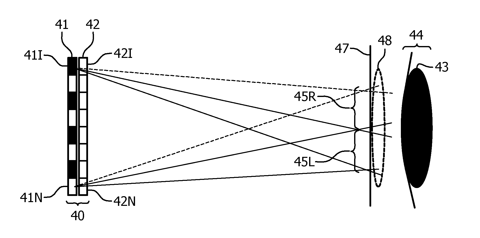
[0091]The invention provides a display device from which a viewer can experience a free focus effect.

[0092]With such a display the light output of the combination of pixels imaged to one given view area of the pupil by the optical unit together can define a subimage of a 3D scene as viewed from a single viewpoint. By this is meant that the view imaged onto this view area and the subimage formed from such a view on the retina of the eye when the pupil of the eye is positioned such that it receives at least part of the view area, corresponds to the view of the 3D scene either from laterally spaced viewpoints with respect to the scene, or from different depth points along a common viewing axis to the 3D scene. The term “viewpoint” should be understood accordingly.

[0093]The light provided to the pupil thus may comprise at least two such subimages of the 3D scene that relate to view points that can be observed simultaneously by one eye of a viewer in real life.

[0094]Therewith, the eye ha...


PUM


Abstract

A display device (40) comprising: a display panel (41) comprising a set of pixels (41R, 41L) the pixels being spatially distributed over the display panel, and each pixel being for providing a light output, the set of pixels comprising a plurality of different subsets (411) of pixels, each subset of pixels comprising one or more pixels of the set of pixels, an imaging unit (42) arranged for imaging the one or more pixels of a subset of pixels to form pixel images on a plurality of view areas on an imaginary plane located at a first distance in front of the display, the plurality of view areas not overlapping each other, with at least one pixel image of each one of the different subsets of pixels overlapping on a same one of the plurality of view areas, the imaginary plane comprising an imaginary circle having the diameter of the pupil of an eye, and the imaginary circle enclosing at least a part of at least two of the plurality of view areas, where the at least two of the plurality of view areas at least partly enclosed within the imaginary circle differ from each other with respect to at least one of the pixel images therein. The display system may be for one eye only or for two eyes of a viewer or for more eyes of more viewers.

Description

FIELD OF THE INVENTION[0001]This invention relates to a display device and method that provide a free focus to the viewer. Particularly, but not exclusively, the invention relates to a stereoscopic display device and method.BACKGROUND OF THE INVENTION[0002]The majority of 2D displays (TV's, computer monitors and display screens of handheld devices) and 3D (auto) stereoscopic displays (displays without requiring the use of viewer aids to perceive stereoscopic images) available today provide a display of images to the viewer that does not enable the viewer to (re)focus on parts of an image of his choice in a natural way like when observing a real life scene.[0003]When viewed from a particular viewpoint, a real life scene in general has objects positioned nearby the viewer and other objects positioned further away from the viewer, i.e. the scene has depth. For example, in a scene there may be a nearby object in the form of a person standing in front of a further away object in the form...

Claims


Application Information

Patent Timeline
IPC IPC(8): H04N13/04H04N13/00H04N13/305H04N13/307
CPCH04N13/0033H04N13/0402H04N13/0406H04N13/144H04N13/302H04N13/307H04N13/305
Inventor KROON, BARTKRIJN, MARCELLINUS PETRUS CAROLUS MICHAELDE BRUIJN, FREDERIK JANJOHNSON, MARK THOMASNEWTON, PHILIP STEVENSALTERS, BART ANDREDE ZWART, SIEBE TJERKKORST, JOHANNES HENRICUS MARIA
Owner KONINKLIJKE PHILIPS ELECTRONICS NV
Why Eureka
Try Eureka